9400001-J1 Rev F
42
CAN termination enabled
CAN termination disabled
If optional shunt mux are installed, the existing outer distribution
bay is connected by a CAN bus cable to the controller. The CAN
bus cable is then daisy-chained to shunt mux in the next distri-
bution bays—see Figure 35.
3. Disconnect the existing controller-to-shunt mux CAN bus
cable.
4. Reconnect the controller to the shunt mux in the outermost
expansion bay with a longer cable from the cable kit.
5. Daisy chain the remaining shunt mux as shown in Figure 35
using cables from the cable kit where necessary.
Expanding and Existing System—CAN Bus Cables:
NOTE:
If your system has redundant rectifiers, it is recommended to power off the left most
rectifier in the top shelf of the existing bay during this procedure.
In your existing system, the CAN Bus is terminated at the highest shelf in the outermost power bay. (See Figure 35
for the sequence of CAN bus cabling)
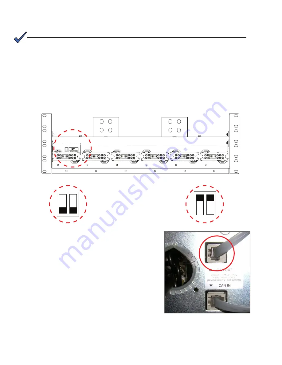
1. Disable termination in its current location and enable termination in the expansion power bay as follows:
a. Remove the left most rectifier in the top shelf of the existing power bay. (Refer to the Rectifier Shelf manual
for the removal and re-insertion procedure.)
b. Flip the DIP switches from Termination Enabled to Termination Disabled—see Figure 37.
c. Replace the rectifier.
Figure 37 — CAN Bus Termination 4.0kW
2. Connect the inter-bay CAN bus cable, which ships with the
expansion bay, to the CAN OUT connector of the top rectifier
shelf of the expansion bay (Figure 38).
Figure 38 — CAN IN/CAN OUT Connection 4.0kW


