9400001-J1 Rev F
56
8.4.3 Battery Return and Load Return Cables
CAUTION!
Do NOT make final connection to battery live. Insulate and leave disconnected or re
-
move the battery fuses. Switch battery contactors off (if used).
Battery cables should be sized for a 0.25V drop from battery to the power system at full load including anticipated
growth. The cables should also meet ampacity requirements.
Connect the battery return cables and the load return cables to the common bus shown in or to the external battery
return busbar if that option is in place. In a multi-bay system, balance battery and load returns evenly between the
bays.
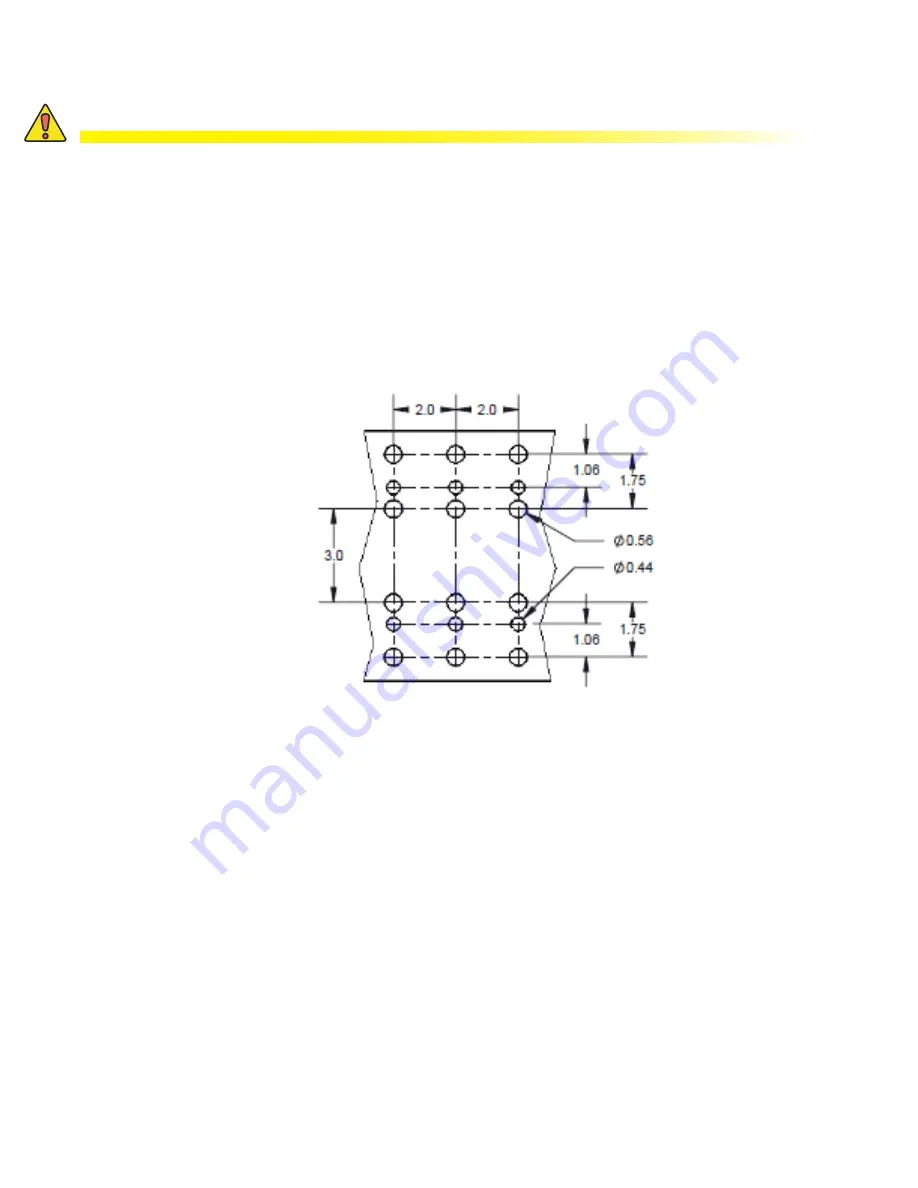
Both busbars are designed for the following connection options:
• 1/2" holes on 1-3/4" centers
• 3/8" holes on 1" centers
Figure 51 — Customer Connections Spacing
8.4.4 -48V Battery Cables
Connect directly to the -48V busbar at the top of the power system bay shown in Figure 20.
8.4.5 DC Cables between the Power System and the Loads
Refer to guidelines supplied with the load equipment. Typically distribution cables are sized to provide a 0.5V loop
drop at full load as well as meeting ampacity requirements of the protection fuse or circuit breaker.
Procedure:
1. Cut cables to length cable and terminate with a two-hole lug.
2. Identify each cable with a label that indicates its location within the distribution modules.
3. Connect the load returns to the overhead busbar in the area of the distribution bays.
4. Neatly group cables with tie wraps.
8.4.6 External Alarms
All applicable alarms should be connected to the local alarm-sending unit from the power system. The system con-
troller provides form “C” relay contacts for interconnection.


