39
9400001-J1 Rev F
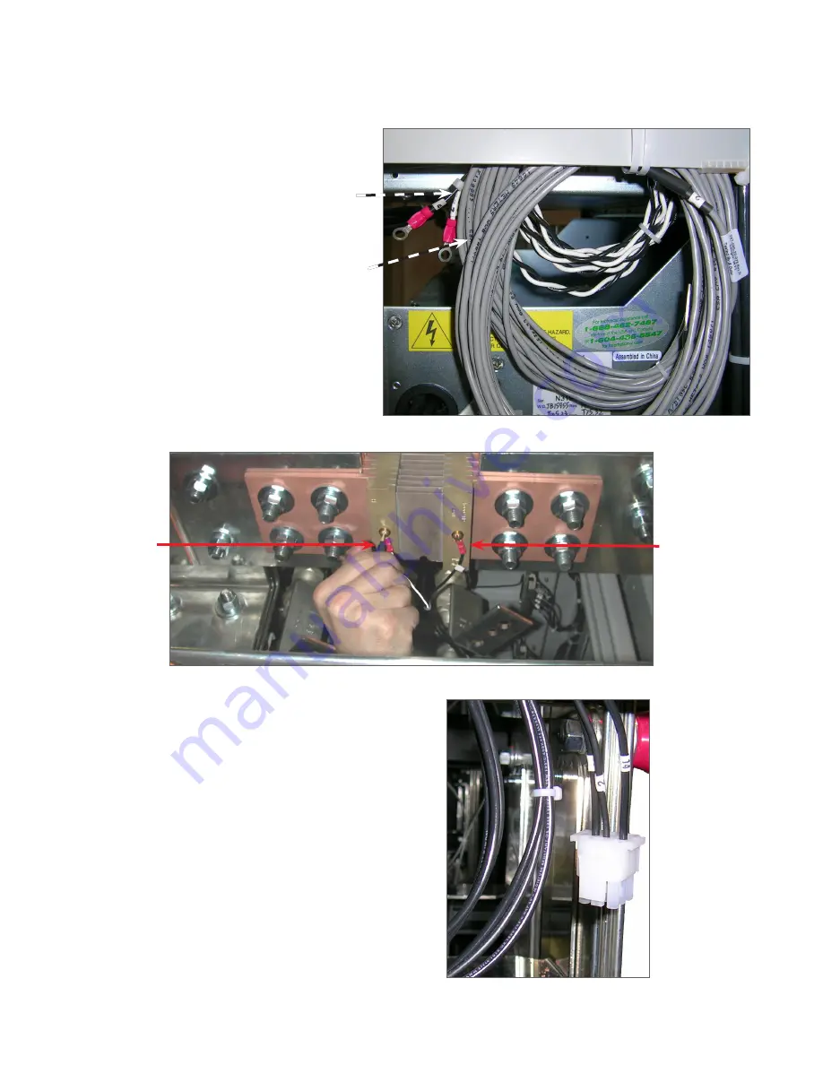
Figure 33 — Inter-bay Wiring Harness
Figure 32 — Shunt Connections
3. Locate and connect the inter-bay alarm signal connectors.
4. Connect the inter-bay alarm signal connectors between
the 2
nd
and 3
rd
frames, the 3
rd
and 4
th
frames, and so on.
2. Connect current shunt leads. Refer to Figure 20 for the location of the shunt in the distribution bay.
1. Locate the coils of cables that are tie-
wrapped to the side of the power bay
containing the controller.
Black and white
shunt wires.
Black wire on
power bay side
White wire on
distribution
bay side
Alarm signal wires.
7.5 Connecting the Shunt and Inter-Bay Signal Cables
This section applies to new installations as well as the installation of expansion distribution and power bays.

