background image

9400001-J1     Rev F

44

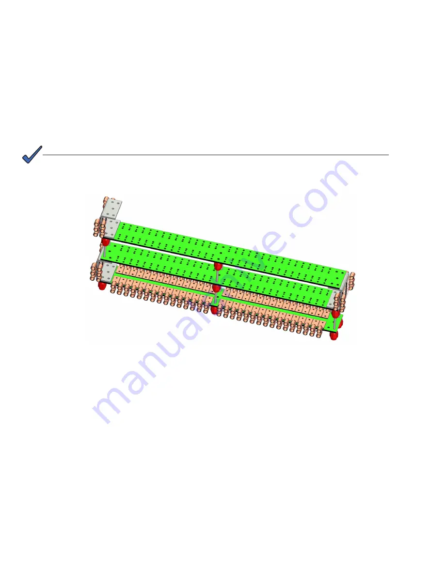
Figure 40  —  External Battery Return Bar Kit

7.6  Mounting the Optional External Return Bar

The expandable external return bar kit (0380039-001) is an option for return connections for the loads and to serve 
as the common connecting point for the positive side of the power bays and the batteries.
The base kit has a 4000A capacity.

1.  Before joining return bar components together, ensure that all contact surfaces on the busbars are clean and 

coated with a thin coat of NO-OX-ID “A” compound (or approved equivalent).

2.  Follow the instructions included with the kit (0380039-F0), to assemble and mount the kit on a customer-

supplied auxiliary framing superstructure away from the system.

NOTE:

Requires customer supplied auxiliary frame (2 " x 9/16").

Summary of Contents for CXPS-C

Page 1: ...Technical Guide 9400001 J1 Effective 11 2018 CXPS C Centralized Power Plant Alpha Technologies Ltd ...

Page 2: ......

Page 3: ...on only and is subject to change without notice While reasonable efforts have been made in the preparation of this document to assure its accuracy Alpha Technologies assumes no liability resulting from errors or omissions in this document or from the use of the information contained herein Alpha Technologies reserves the right to make changes in the product design without reservation and with out ...

Page 4: ......

Page 5: ...ays 16 4 4 DC Inter bay Copper 25 4 5 Cordex HP Controller 27 4 6 External Peripherals 28 5 Pre Installation Preparation 31 5 1 Site Selection 31 5 2 Tools and Test Equipment 32 5 3 Floor Loading 32 6 Inspection 33 6 1 Packing Materials 33 6 2 Check for Damage 33 6 3 General Receipt of Shipment 33 7 Frame Installation 34 7 1 Floor Drilling for Standard Anchoring 34 7 2 Placing and Securing the Bay...

Page 6: ... 9 1 Standalone Power Bay 57 9 2 Standalone Distribution Bay 58 10 System Startup 59 10 1 Check System Connections 59 10 2 Verify AC and Power the Rectifier Shelf 59 10 3 Check Battery Polarity and Connect 59 10 4 Final Configuration and Test 59 10 5 Shelf ID Connection 60 11 Test and Commissioning Overview 61 11 1 System 61 11 2 Battery 61 11 3 Documentation 61 12 Maintenance 62 12 1 Rectifiers 6...

Page 7: ... High Capacity Breaker 20 Figure 13 2x 5 Position High Capacity Breaker 20 Figure 14 2x 6 Position High Capacity Breaker 21 Figure 15 4x2 4x1 Position High Capacity Breaker 21 Figure 16 18 Position Bullet Breaker 22 Figure 17 18 Position Bullet Breaker Return 22 Figure 18 Distribution Bay DC Distribution Bus 23 Figure 19 Distribution Shunts 24 Figure 20 Inter bay DC Connections 25 Figure 21 Extern...

Page 8: ... Figure 40 External Battery Return Bar Kit 44 Figure 41 Battery Installation 45 Figure 42 Battery Temperature Probes 46 Figure 43 Battery Return Busbars Frame Ground and Battery Return Reference 50 Figure 44 AC Distribution 51 Figure 45 Pre Wired 8 feed AC Panel 3 Phase 3 Wire 208 480 Vac 52 Figure 46 Terminal Blocks for 8 feed 3 wire 208 480Vac input 53 Figure 47 Terminal Blocks for 16 feed 208 4...

Page 9: ...EVENT INJURY OR DEATH to personnel Warnings are indicated by a shock hazard icon the word WARNING and a rule beneath which the information appears WARNING You must read and understand the following warnings before installing the enclosure and its component Failure to do so could result in personal injury or death CAUTION CAUTION indicates safety information intended to PREVENT DAMAGE to material o...

Page 10: ...ny installation or removal procedure Ensure that no liquids or wet clothes come into contact with internal components Hazardous electrically live parts inside this unit are energized from the batteries even when the AC input power is disconnected The enclosure which contains the DC or AC power system must remain locked at all times except when authorized service personnel are present Always assume...

Page 11: ...d inter bay copper busbars Figure 1 The Power bay converts AC to fully regulated and filtered 48Vdc power which is fed through a load shunt to the Distribution Bay The system can be expanded from the center out to a full 12 000A capacity system using the CXC HP controller The system is configurable in 4000A 8000A and 12000A CXC HP capacity 2 2 Part Numbers and List Options The system offers severa...

Page 12: ...es rectifier side of the shunt Single Power bay 11 X 1 2 on 1 3 4 centers or 24 x 3 8 on 1 centers Each Additional Power bay 14 X 1 2 on 1 3 4 centers or 14 x 3 8 on 1 centers Number of landings on the load side of the shunt to feed unfused power to remote distribution Single Distribution Bay 14 X 1 2 on 1 3 4 centers or 11 X 3 8 on 1 centers Each Additional Distribution Bay 14 X 1 2 on 1 3 4 cent...

Page 13: ... Auxiliary framing customer supplied Termination With 3 horizontal bars 202 sets of 1 2 holes on 1 3 4 centers or 202 sets of 3 8 holes on 1 centers Unit capacity per bay 4000A Ultimate capacity 12 000A 3 bay limit Table C Distribution Panels Panel Type Busbar Quantity Rating Max Rating per Panel Output Termination TPL Fuses 61 to 800A up to 24 per distribution bay 2000A 2 hole 1 2 dia on 1 3 4 ce...

Page 14: ...ers Number of landings on the load side of the shunt to feed unfused power to remote distribution Single distribution bay 14 X 1 2 on 1 3 4 centers or 11 x 3 8 on 1 centers Each additional power bay 14 X 1 2 on 1 3 4 centers or 14 x 3 8 on 1 centers Internal return bar Overhead bus ground 24 sets of 2 hole 1 2 dia on 1 3 4 centers or 3 8 dia on 1 centers basic one power plus one distribution bay 1...

Page 15: ...s or 1x 2000A power bay 4 shelves 1x 6000A distribution bay System controller Expandable to include 1x or more additional 4000A power bay 8000A or 12000A system capacity 1x or more additional 2000A power bay 4000A 6000A 8000A 10000A or 12000A system capacity 1x or more additional 6000A distribution bays 12000A distribution capacity Distribution bay Power bay Controller AC Distribution Assembly 8x ...

Page 16: ...es A Cordex HP 4 0kW rectifier supplies a nominal output of 74A at 54Vdc and the 12kW 480 rectifier supplies 222A at 54Vdc nominal Rectifier specifications are included in the Cordex HP rectifier manual included with the system documentation package The controller provides central control of the rectifiers output level load sharing temperature compensation low voltage disconnect on the distributio...

Page 17: ... an inter bay return bar located across the top of the power and distribution bays Similarly the 48V vertical busbar connects to an inter bay 48V busbar which terminates at the system shunt located in the distribution bay Figure 4 shows a top view of the horizontal busbars between a power bay and two distribution bays Return 48V FRONT REAR Power Bay Distribution Bay Inter bay return busbar Inter b...

Page 18: ...Ds Rectifier status such as mains OK Minor and Major alarms display on the rectifier front panel A rectifier Major alarm indicates the module has shut down due to a critical fault A rectifier Minor alarm indicates the module has a non critical alarm however it has not shut down See the Cordex HP rectifier manual included with the system documentation package for detailed information LEDs LEDs Figu...

Page 19: ...er Max 6 fuse tiers per bay Bolt in breakers high capacity 1 pole 100 to 250A 2000A 12 breaker poles per tier Max 6 panels per bay 2 pole 300 to 400A 3 pole 500 to 700A 4 pole 800A 5 pole 1000A 6 pole 1200A Plug in bullet breakers 1 pole up to 100A 600A 18 breaker poles per tier Max 12 tiers per bay 100A and 125A breakers fuses need one breaker space between breaker and breaker beside it 2 pole 11...

Page 20: ...17 9400001 J1 Rev F Bullet breaker tier LVD inhibit High capacity breaker tier TPL fuse tiers Distribution panel alarm indicator Figure 7 Distribution Panel Options ...

Page 21: ... 1 center or 1 2 dia on 1 3 4 center Option for whole Tier LVD 2000A disconnect 4 3 2 12x 1 Position high Capacity Breaker Tier Features Occupies 1 tier positions 2000A tier rating Can accept 1P 250A max high capacity breaker Individually monitored by 300A Shunts 1x landings per position 2 hole 3 8 dia on 1 center Option for whole Tier LVD 2000A disconnect Figure 8 4 Position TPL Figure 9 12x 1 Po...

Page 22: ...2 dia on 1 3 4 center Option for whole Tier LVD 2000A disconnect 4 3 4 4x 3 Position high Capacity Breaker Tier Feature Occupies 1 tier positions 2000A tier rating Can accept 3P 500A 700A high capacity breaker Individually monitored by 1000A Shunts 2x landings per position 2 hole 3 8 dia on 1 center 1 2 dia on 1 3 4 center Option for whole Tier LVD 2000A disconnect Figure 10 6x 2 Position High Cap...

Page 23: ...2 dia on 1 3 4 center Option for whole Tier LVD 2000A disconnect 4 3 6 2x 5 Position high Capacity Breaker Tier Features Occupies 1 tier positions 2000A tier rating Can accept 5P 1000A high capacity breaker Individually monitored by 1500A Shunts 2x landings per position 2 hole 3 8 dia on 1 center 1 2 dia on 1 3 4 center Option for whole Tier LVD 2000A disconnect Figure 12 3x 4 Position High Capaci...

Page 24: ...x 2 4x 1 Position high Capacity Breaker Tier Features Occupies 1 tier positions 2000A tier rating Can accept 4x1P 250A Max high capacity breaker Can accept 4x 2p 300A 400A high capacity breaker Individually monitored by 400A and 800A Shunts 1 Position 1x landings per position 2 hole 3 8 dia on 1 center 2 Position 2x landings per position 2 hole 3 8 dia on 1 center 1 2 dia on 1 3 4 center Option fo...

Page 25: ...monitoring by 800A Shunt 1P breaker fuse 1 pole 2 hole 1 4 dia on 5 8 center 2P 3P 2 hole 3 8 dia on 1 center via adaptors Option for whole tier LVD 600A disconnect 100A and 125A breakers fuses need one breaker space 4 3 10 18 Position Bullet Breaker Return Feature Occupies 1 2 tier positions 600A tier rating Figure 16 18 Position Bullet Breaker Figure 17 18 Position Bullet Breaker Return ...

Page 26: ... Bus 4 3 11 DC Distribution Buses Each distribution bay has a vertical distribution bus see Figure 18 that brings power from the overhead busbars down into the bay This bus is rated for 6000A continuous operation LVD contactor optional Main vertical busbar Shunts ...

Page 27: ... distribution panel can be ordered with its own disconnect contactor The LVLD option can be configured at time of order for group control Contactor ratings are 2000A for TPL bolt in breaker and 600A for plug in bullet panel Systems with LVLDs are equipped with a manual override switch The purpose of this switch is to allow the user to manually bypass the CXC HP control of the LVLDs during maintena...

Page 28: ...lable in 4000A 8000A and 12000A nominal sizing as required Maximum continuous load ratings are 80 due to shunt capability All live inter bay bus work is contained within the system cabinets Re turn busbars can be factory ordered as internal for smaller systems with 12 or less large capacity circuits or external for systems with more than 12 distribution circuits Figure 20 shows 12000A buswork with...

Page 29: ...the bays interconnecting the vertical 48Vdc distribution buses in each bay There are 11 termination points on a basic power system 4 4 4 External Return Bar Optional This option is available to facilitate termination of a high quantity of large cables In addition relocating the return cables outside the bay frees up space within the bay for load cables The external return bar is required for syste...

Page 30: ...reen display to access controls and menu items by using fingertip touch or a stylus Home button provides the ability to go directly back to the home screen from any menu Front panel reset for emergency use only to restart the controller if the unit touch screen or home button are not responding Front panel LEDs for alarms progress and status indication Audio speaker built in audio tones during act...

Page 31: ...A 25mV The input range for this signal is 250mV to 250mV Four temperature input channels T1 T4 provide monitoring of temperature probes thermistors These are typi cally used for either ambient temperature or for battery post monitoring to enable battery temperature compensa tion The temperature sensor is provided by Alpha in various lengths The input range for this signal is 0V to 5V and is powere...

Page 32: ...tion should be used whenever performing controller maintenance such as test relay functions or when replacing a controller To engage the LVD override function press and hold the button for three seconds A yellow indicator LED will signal that the override is engaged To restore back to normal LVD operation press and hold the LVD button again for three seconds 4 6 2 6I ADIO The 6I ADIO is an analog ...

Page 33: ...ay ID peripheral enables users to identify individual 12kW 480 3 Phase rectifier modules by their specific bay and shelf location within the system This peripheral is an independent module which broadcasts information directly to the rectifier modules 12kW 480 rectifiers can then communicate the specific bay shelf and slot identification back to the master controller The controller s LCD screen an...

Page 34: ...the power system to meet the cooling requirements of the rectifiers in the power system and to allow easy access to the power system components Consider the following before selecting a location for the CXPS C power system Structure of building able to support the additional weight Enough space to meet requirements for access Enough space to meet cooling requirements of the rectifiers Adequate spa...

Page 35: ...ft lb for system connections Insulating canvases as required 2 x 2 1 x 1 3 x 3 etc Cutters and wire strippers 14 to 22 AWG 2 5 34 mm2 Insulated hand tools listed below Combination wrenches Ratchet and socket set Various screwdrivers Electricians knife Fine tipped slot screwdriver tweaker Cable cutters 5 3 Floor Loading 5 3 1 Concrete floors for reference only Concrete floor installation requiring ...

Page 36: ...roduct is packed with at least three inches of shock absorbing material to prevent shipping damage Alpha Technologies is not responsible for damage caused by improper packaging of returned products 6 2 Check for Damage Before unpacking the product note any damage to the shipping container Unpack the product and inspect the exterior for damage If any damage is observed contact the carrier immediate...

Page 37: ...is earthquake qualified when properly anchored to a 3000 psi 2 11 kg per sq mm concrete floor The anchoring kit and procedures in this section are for a seismic installation but apply equally well to a non seismic installation 7 1 1 Drilling the Holes for the Anchor Bolts 1 If you are installing more than one bay snap a chalk line on the floor to align the bays for mounting 2 Use a rebar locator t...

Page 38: ...ck that the bay is level front to back and side to side Figure 29 Securing Power System to Concrete Floor NOTE When installing two or more adjacent bays install the inter bay DC components per section 7 4 before completing the final torquing of the anchor bolts 4 Once the bay is level tighten all bolts to the appropriate torque supplied by the anchor manufacturer CAUTION It is extremely important ...

Page 39: ... Securing Adjacent Bays Locate the bay to bay bolting kits that ship with the equipment Bolt each pair of bays to gether Remove horizontal braces to make it easier to install horizontal busbars Remove the top flange at the front of the bay to access anchoring holes ...

Page 40: ...80036 002 F0 8000A Busbar connectivity kit with internal ground 0380036 003 F0 4000A Busbar connectivity kit with internal ground 0380038 001 F0 12000A Busbar connectivity kit with external ground 0380038 002 F0 8000A Busbar connectivity kit with external ground 0380038 003 F0 4000A Busbar connectivity kit with external ground 0380039 F0 External return bar kit 4000A 0380040 F0 Legacy busbar conne...

Page 41: ...emble the inter bay bus work with the bolts that ship in the kit with the copper buses 2 Once assembled torque all bolts to 75 ft lbs 3 Proceed with final setting of the bay floor anchors Figure 31 Example of Installed Inter bay Buswork ...

Page 42: ...ent shunt leads Refer to Figure 20 for the location of the shunt in the distribution bay 1 Locate the coils of cables that are tie wrapped to the side of the power bay containing the controller Black and white shunt wires Black wire on power bay side White wire on distribution bay side Alarm signal wires 7 5 Connecting the Shunt and Inter Bay Signal Cables This section applies to new installations...

Page 43: ...shelf of the primary power bay 5 Terminate the top rectifier shelf of the primary power bay 6 For connection to the extension power bay remove the CAN terminator from the L ADIO and connect the CAN bus from CAN OUT on the L ADIO to the bottom rectifier shelf of the adjacent power bay 7 Repeat the preceding step for all power bays working from the inner most out 8 Terminate the top shelf of the out...

Page 44: ...sion Bay Extension Power Bay s Shelf Bay ID 1 4 8 12 Shelf Bay ID 1 4 8 12 CAN OUT Terminated CAN IN Top rectifier shelf Shelf ID CAN OUT Terminated CAN IN Top rectifier shelf Shelf ID CAN OUT Terminated CAN IN Rectifier shelf Shelf ID CAN OUT Terminated CAN IN Rectifier shelf Shelf ID CAN OUT Terminated CAN IN Rectifier shelf bottom Shelf ID CAN OUT Terminated CAN IN Rectifier shelf bottom Shelf ...

Page 45: ...t is recommended to power off the left most rectifier in the top shelf of the existing bay during this procedure In your existing system the CAN Bus is terminated at the highest shelf in the outermost power bay See Figure 35 for the sequence of CAN bus cabling 1 Disable termination in its current location and enable termination in the expansion power bay as follows a Remove the left most rectifier...

Page 46: ...eparately If battery disconnect contactors are used 1 Connect a secondary power source from either side of the LVBD to the controller Refer to 4 6 3 Redundant Input Power Module on page 30 2 Connect battery disconnect panels to the controller s battery fuse alarm input and LVBD control ...

Page 47: ...e of the power bays and the batteries The base kit has a 4000A capacity 1 Before joining return bar components together ensure that all contact surfaces on the busbars are clean and coated with a thin coat of NO OX ID A compound or approved equivalent 2 Follow the instructions included with the kit 0380039 F0 to assemble and mount the kit on a customer supplied auxiliary framing superstructure awa...

Page 48: ...ttery breakers DC circuit breakers and fuses on the distribution panels are either in the OFF position or removed Use a corrosion inhibiting agent such as NO OX or NCP 2 on all battery terminal connections 1 Assemble battery rack if required and the cells or mono blocks as per the installation instructions supplied with the batteries 2 Ensure that the battery output cabling will reach the and term...

Page 49: ...ct temperature probes from controller to battery termination post negative 3 Pick a location at mid height on one or more battery strings which will provide a good average temperature reading i e away from heating or cooling sources Figure 42 Battery Temperature Probes NOTE Connect both temperature probes to separate battery posts for a better average read ing of the battery ...

Page 50: ...________________________________________ Battery location and or number _______________________________________________________________ No of cells _______________ Type __________________________ Date new _______________________ Date installed __________________ Float voltage ____________________ Ambient temp ______________ Table G Typical VRLA battery maintenance report Cell Serial Voltage Specif...

Page 51: ...wires for example alarms from the controller interfacing with the outside world exit the frame through the top or bottom 8 1 2 Calculating Output Wire Size Requirements Although DC power wiring and cabling in telecommunication applications tend to ex ceed electrical code requirements mostly due to the voltage drop requirements all applicable electrical code s take precedence over the guidelines an...

Page 52: ...AWG or 4 0 211600 107 2 120 313 MCM or kcmil 313600 159 150 or 185 350 MCM or kcmil 350000 177 36 185 373 MCM or kcmil 373700 189 185 or 240 500 MCM or kcmil 500000 253 36 300 535 MCM or kcmil 535300 271 300 750 MCM or kcmil 750000 380 00 400 777 MCM or kcmil 777700 394 400 8 1 3 Recommended Torque Values Recommended torque values for connection to the power system Clear hole connections nut and b...

Page 53: ...tection fuse or circuit breaker 750 MCM is recommended This is the minimum require ment Other factors including length of cable and special grounding requirements of the load must be factored in Use two hole crimp type lugs and insulated cable that does not have any tight bends or kinks Optional external battery return bar Unless specifically instructed otherwise the battery return reference BRR l...

Page 54: ...nal Recommend ed Breaker A Connection Type Recommend ed Wire Size AWG Knockout Dimension in Knockout Quantity 4 0kW Rectifier 2000A 4000A 4 8 208 100 3W PE 2 2 0 1 5 KO 8 2000A 4000A 4 8 277 480 50 3W N PE 6 1 5 1 25 KO 8 2000A 4000A 8 16 208 50 3W PE 6 1 5 1 25 KO 16 2000A 4000A 8 16 277 480 30 3W N PE 8 1 5 1 25 KO 16 4000A 6 277 480 60 3W N PE 6 1 5 1 25 KO 8 12kW 480 Rectifier 2000A 4000A 4 8 ...

Page 55: ...AC breakers are off and locked out at the AC Input Panel NOTE Wire one side at a time with only one door open Working with both doors open may make it difficult to close both doors when the wiring is complete Figure 45 Pre Wired 8 feed AC Panel 3 Phase 3 Wire 208 480 Vac Knockouts ...

Page 56: ...kouts in the top of the assembly 2 Connect to the terminal blocks as shown in this figure Also clearly labeled on the panel 3 Neatly group cables with tie wraps Figure 46 Terminal Blocks for 8 feed 3 wire 208 480Vac input Figure 47 Terminal Blocks for 16 feed 208 480Vac input Figure 48 Terminal Blocks for 6 feed 480Vac input ...

Page 57: ... for the breaker alarm to the left terminal block located on the front bottom of the distribution shelf Connect the Normally Closed contact to the right terminal block located on the front bottom of the distribution shelf See Figure 49 NOTE Use 18 22 AWG Wires Figure 49 High Capacity Breaker Panel Alarm Wiring ...

Page 58: ...2 2000A Power bay 3 5x 750MCM min 10x 750MCM min 10x 750MCM min To Master Ground Bus External battery return bar Power bay positive return detail 8 4 2 External Battery Return Bar Wiring Connect the external battery return bar s to the associated power bay positive return detail as shown in Figure 50 ...

Page 59: ...s on 1 centers Figure 51 Customer Connections Spacing 8 4 4 48V Battery Cables Connect directly to the 48V busbar at the top of the power system bay shown in Figure 20 8 4 5 DC Cables between the Power System and the Loads Refer to guidelines supplied with the load equipment Typically distribution cables are sized to provide a 0 5V loop drop at full load as well as meeting ampacity requirements of...

Page 60: ...bay and MGB or FGB 813 X 3 00 mounting slots 6 places 7 60ʺ 12 80ʺ 7 60ʺ 1 50ʺ 3 75ʺ 20 50ʺ 3 75ʺ 3 30ʺ 3 30ʺ 21 40ʺ 3 Refer to section 8 3 on page 51 to connect AC input to the AC distribution assembly at the top of the unit 4 Connect the power bay positive return detail to the existing system overhead battery return bus 5 Connect the power bay Hot detail to the existing system overhead Hot power...

Page 61: ... distant devices 1 Secure the bay to the floor See section 9 1 on page 57 2 Connect a cable typically a 2 0 cable between the frame of the bay and MGB or FGB 3 Run cable from the existing system overhead Hot power bus to the customer connection busbar in the distribution bay 7 X 1 2 on 1 75 centers OR 7 X 3 8 on 1 centers 1 X 1 2 on 1 75 centers OR 1 X 3 8 on 1 centers ...

Page 62: ...r set the battery parameters float and equalize voltages to the capacity Peukert exponent open circuit voltage levels specified by the battery manufacturer 10 4 Final Configuration and Test 1 Configure other system parameters as required changing the low and high voltage AC and DC warning and cutout limits for example 2 At this point there should be no alarms present Investigate and correct any al...

Page 63: ...RJ12 connection located on right side of rectifier shelf pre installed from the factory IP 2 x 12kW Rectifier Slot IDs 2 x 12kW Rectifier Slot IDs Bay ID 1 Shelf ID 1 Bay ID 1 Shelf ID 1 Bay ID 1 Shelf ID 2 Bay ID 1 Shelf ID 2 CAN driver Cordex HP J1 J12 J11 J10 J2 J3 J4 J5 J6 J7 J8 J9 CAN bus transmits bay ID shelf ID and rectifier slot IDs to CXC HP Rack mounted Shelf ID PCB Bay ID 1 manually se...

Page 64: ...avity cell voltage charge current and temperature Battery warranty may be void if batteries are not initially charged following the manufacture s guidelines with proper records maintained Some VRLA batteries do not require initial charging if placed on charge within 3 6 months of manufacture check with the manufacturer After the equalization period battery voltage should be reduced to the recommen...

Page 65: ... alarm relay operation 12 1 Rectifiers It is recommended that every five years MOV surge suppressors are replaced especially in areas of high lightning activity See Cordex HP rectifier manual for general maintenance information 12 2 Batteries It is recommended that checks are made every six months for battery voltage conductance temperature imped ance connections etc See battery manufacturer s man...

Page 66: ... or consequential damages based upon equipment failure during or after the warranty period No other obligations are expressed or implied Warranty also does not cover damage or equipment failure due to cause s external to the unit including but not limited to environmental conditions water damage power surges or any other external influence The customer is responsible for all shipping and handling ...

Page 67: ...C Federal Communications Commission for the USA GSM Group Speciale Mobile global system for mobile communications HVSD High voltage shutdown IEC International Electrotechnical Commission IEEE Institute of Electrical and Electronics Engineers IP Internet Protocol LED Light emitting diode LVD Low voltage disconnect MIL One thousandth of an inch used in expressing wire cross sectional area MOV Metal ...

Page 68: ... certified to CSA C22 2 No 107 3 and UL 1778 As part of the reciprocal US Canada agreement regarding testing laboratories the Standards Council of Canada Canada s national accreditation body granted Underwriters Laboratories UL authority to certify products for sale in Canada 2 Only Underwriters Laboratories may grant a licence for the use of this mark which indicates compliance with both Canadian...

Page 69: ...010 PRODUCT TO BE FABRICATED ACCORDING TO ATL PRODUCTION STANDARD 0700001 1 CUSTOMER CONNECTION BUSBAR LOCATION DIMENSIONS ARE FROM THE REAR OUTSIDE EDGE OF THE 2 ENCLOSURES TO THE FRONT FACES OF THE CUSTOMER CONNECTION BUSBARS AND FROM THE LEFT OUTSIDE EDGE OF THE ENCLOSURE TO THE LEFT EDGES OF THE CUSTOMER CONNECTION BUSBARS NOTES UNLESS OTHERWISE SPECIFIED 28 0 TYP 28 0 TYP 84 0 TYP RECTIFIER B...

Page 70: ... 22 12 OCT 22 12 S BIENKO X X X XX X XXX ANGULAR THIRD ANGLE PROJECTION UNLESS OTHERWISE SPECIFIED DIM ARE IN INCHES INTERPRET DIM AND TOL PER ASME Y14 5 1994 0 040 1 0 020 0 010 PRODUCT TO BE FABRICATED ACCORDING TO ATL PRODUCTION STANDARD 0700001 1 CUSTOMER CONNECTION BUSBAR LOCATION DIMENSIONS ARE FROM THE REAR OUTSIDE EDGE OF THE 2 ENCLOSURES TO THE FRONT FACES OF THE CUSTOMER CONNECTION BUSBA...

Page 71: ...ONSENT ALPHA TECHNOLOGIES LTD CHECKED DRAWN DATE APPROVALS C COOMBES OCT 22 12 OCT 22 12 S BIENKO X X X XX X XXX ANGULAR THIRD ANGLE PROJECTION UNLESS OTHERWISE SPECIFIED DIM ARE IN INCHES INTERPRET DIM AND TOL PER ASME Y14 5 1994 0 040 1 0 020 0 010 PRODUCT TO BE FABRICATED ACCORDING TO ATL PRODUCTION STANDARD 0700001 1 CUSTOMER CONNECTION BUSBAR LOCATION DIMENSIONS ARE FROM THE REAR OUTSIDE EDGE...

Page 72: ...E PROJECTION UNLESS OTHERWISE SPECIFIED DIM ARE IN INCHES INTERPRET DIM AND TOL PER ASME Y14 5 1994 0 040 1 0 020 0 010 PRODUCT TO BE FABRICATED ACCORDING TO ATL PRODUCTION STANDARD 0700001 1 CUSTOMER CONNECTION BUSBAR LOCATION DIMENSIONS ARE FROM THE REAR OUTSIDE EDGE OF THE 2 ENCLOSURES TO THE FRONT FACES OF THE CUSTOMER CONNECTION BUSBARS AND FROM THE LEFT OUTSIDE EDGE OF THE ENCLOSURE TO THE L...

Page 73: ...TANDARD 0700001 1 CUSTOMER CONNECTION BUSBAR LOCATION DIMENSIONS ARE FROM THE REAR OUTSIDE EDGE OF THE 2 ENCLOSURES TO THE FRONT FACES OF THE CUSTOMER CONNECTION BUSBARS AND FROM THE LEFT OUTSIDE EDGE OF THE ENCLOSURE TO THE LEFT EDGES OF THE CUSTOMER CONNECTION BUSBARS NOTES UNLESS OTHERWISE SPECIFIED 28 0 TYP 28 0 TYP 28 0 TYP 84 0 TYP 84 0 3 6 TYP RECTIFIER BAY MAXIMUM 3 RECTIFIER BAYS PER SYST...

Page 74: ... ENCLOSURE TO THE LEFT EDGES OF THE CUSTOMER CONNECTION BUSBARS NOTES UNLESS OTHERWISE SPECIFIED 28 00 TYP 5 8 63 7 00 19 13 15 00 7 00 15 00 15 13 8 63 19 13 19 38 28 00 TYP 28 00 TYP 7 38 8 63 DISTRIBUTION BAY MAXIMUM 6 DISTRIBUTION BAYS PER SYSTEM ADDITIONAL DISTRIBUTION BAY RECTIFIER BAY RECTIFIER BAY RECTIFIER BAY FRONT BACK FRONT FACE OF CUSTOMER CONNECTION BUSBAR RETURN SIDE OUTSIDE EDGES O...

Page 75: ...ES OF THE CUSTOMER CONNECTION BUSBARS AND FROM THE LEFT OUTSIDE EDGE OF THE ENCLOSURE TO THE LEFT EDGES OF THE CUSTOMER CONNECTION BUSBARS NOTES UNLESS OTHERWISE SPECIFIED 28 00 TYP 84 00 TYP 4 40 15 00 5 28 00 TYP 15 00 15 13 7 00 DISTRIBUTION BAY MAXIMUM 6 DISTRIBUTION BAYS PER SYSTEM ADDITIONAL DISTRIBUTION BAY RECTIFIER BAY RECTIFIER BAY RECTIFIER BAY OUTSIDE EDGES OF ENCLOSURE FRONT VIEW OF S...

Page 76: ...NECTION BUSBARS NOTES UNLESS OTHERWISE SPECIFIED DISTRIBUTION BAY RECTIFIER BAY RECTIFIER BAY RECTIFIER BAY 14 X 1 2 ON 1 75 CENTERS OR 14 X 3 8 ON 1 CENTERS RETURN SIDE 14 X 1 2 ON 1 75 CENTERS OR 14 X 3 8 ON 1 CENTERS RETURN SIDE 24 X 1 2 ON 1 75 CENTERS OR 24 X 3 8 ON 1 CENTERS RETURN SIDE 14 X 1 2 ON 1 75 CENTERS OR 14 X 3 8 ON 1 CENTERS HOT SIDE 14 X 1 2 ON 1 75 CENTERS OR 14 X 3 8 ON 1 CENTE...

Page 77: ... 010 PRODUCT TO BE FABRICATED ACCORDING TO ATL PRODUCTION STANDARD 0700001 1 CUSTOMER CONNECTION BUSBAR LOCATION DIMENSIONS ARE FROM THE REAR OUTSIDE EDGE OF THE 2 ENCLOSURES TO THE FRONT FACES OF THE CUSTOMER CONNECTION BUSBARS AND FROM THE LEFT OUTSIDE EDGE OF THE ENCLOSURE TO THE LEFT EDGES OF THE CUSTOMER CONNECTION BUSBARS NOTES UNLESS OTHERWISE SPECIFIED 28 0 TYP 84 0 TYP 69 9 8 1 8 10 1 88 ...

Page 78: ...NLESS OTHERWISE SPECIFIED DIM ARE IN INCHES INTERPRET DIM AND TOL PER ASME Y14 5 1994 0 040 1 0 020 0 010 PRODUCT TO BE FABRICATED ACCORDING TO ATL PRODUCTION STANDARD 0700001 1 CUSTOMER CONNECTION BUSBAR LOCATION DIMENSIONS ARE FROM THE REAR OUTSIDE EDGE OF THE 2 ENCLOSURES TO THE FRONT FACES OF THE CUSTOMER CONNECTION BUSBARS AND FROM THE LEFT OUTSIDE EDGE OF THE ENCLOSURE TO THE LEFT EDGES OF T...

Page 79: ... XXX ANGULAR THIRD ANGLE PROJECTION UNLESS OTHERWISE SPECIFIED DIM ARE IN INCHES INTERPRET DIM AND TOL PER ASME Y14 5 1994 0 040 1 0 020 0 010 ITEM QTY NOTES PRODUCT TO BE FABRICATED ACCORDING TO ATL PRODUCTION STANDARD 0700001 1 CUSTOMER CONNECTION BUSBAR LOCATION DIMENSIONS ARE FROM THE REAR OUTSIDE EDGE OF THE 2 ENCLOSURES TO THE FRONT FACES OF THE CUSTOMER CONNECTION BUSBARS AND FROM THE LEFT ...

Page 80: ...FIED DIM ARE IN INCHES INTERPRET DIM AND TOL PER ASME Y14 5 1994 0 040 1 0 020 0 010 ITEM QTY NOTES PRODUCT TO BE FABRICATED ACCORDING TO ATL PRODUCTION STANDARD 0700001 1 CUSTOMER CONNECTION BUSBAR LOCATION DIMENSIONS ARE FROM THE REAR OUTSIDE EDGE OF THE 2 ENCLOSURES TO THE FRONT FACES OF THE CUSTOMER CONNECTION BUSBARS AND FROM THE LEFT OUTSIDE EDGE OF THE ENCLOSURE TO THE LEFT EDGES OF THE CUS...

Page 81: ...X ANGULAR THIRD ANGLE PROJECTION UNLESS OTHERWISE SPECIFIED DIM ARE IN INCHES INTERPRET DIM AND TOL PER ASME Y14 5 1994 0 040 1 0 020 0 010 ITEM QTY NOTES PRODUCT TO BE FABRICATED ACCORDING TO ATL PRODUCTION STANDARD 0700001 1 CUSTOMER CONNECTION BUSBAR LOCATION DIMENSIONS ARE FROM THE REAR OUTSIDE EDGE OF THE 2 ENCLOSURES TO THE FRONT FACES OF THE CUSTOMER CONNECTION BUSBARS AND FROM THE LEFT OUT...

Page 82: ...FIED DIM ARE IN INCHES INTERPRET DIM AND TOL PER ASME Y14 5 1994 0 040 1 0 020 0 010 ITEM QTY NOTES PRODUCT TO BE FABRICATED ACCORDING TO ATL PRODUCTION STANDARD 0700001 1 CUSTOMER CONNECTION BUSBAR LOCATION DIMENSIONS ARE FROM THE REAR OUTSIDE EDGE OF THE 2 ENCLOSURES TO THE FRONT FACES OF THE CUSTOMER CONNECTION BUSBARS AND FROM THE LEFT OUTSIDE EDGE OF THE ENCLOSURE TO THE LEFT EDGES OF THE CUS...

Page 83: ......

Page 84: ...uite 101 Andrea Chambers P O Box 56468 3307 Limassol Cyprus Tel 357 25 375 675 Fax 357 25 359 595 www alpha com Alpha Technologies Pty Ltd Level 7 91 Phillip Street Parramatta NSW 2150 Australia Tel 61 2 8599 6960 www alpha com Alpha Innovations Brasil Address Rua Alvares Cabral Nº 338 Diadema SP 09981 030 Brazil Tel 55 1 1 2476 0150 www alphainnovations com br Alpha Innovations S A 1 Avenue Alexa...

Reviews: