34
Alpha E-Tec 25R - Routine Servicing
7.1 IMPORTANT NOTES PRIOR TO SERVICING
1. Check the entire flue length and joints including the flue terminal outside. Ensure that all of the flue assembly has been
installed correctly and there are no blockages.
2. Run the boiler and check the operation of its controls.
3. Ensure that all system connections and fittings are sound. Remake any joints and check the tightness of any fittings that
may be leaking.
4. Refill and vent (re-pressurise if sealed) the system as necessary. (Refer to Commissioning, Section 6.1).
For sealed systems -
If the system pressure exceeds 2.5 bar when operating at maximum temperature, the heating
expansion vessel should be checked and re-pressurised, if necessary.
Note: 1.
Check the expansion vessel charge only when the system pressure is zero.
5. Check that the condensate trap drain pipe is connected and all joints are sound.
6. Record details of the service in the Service Record at the back of these instructions.
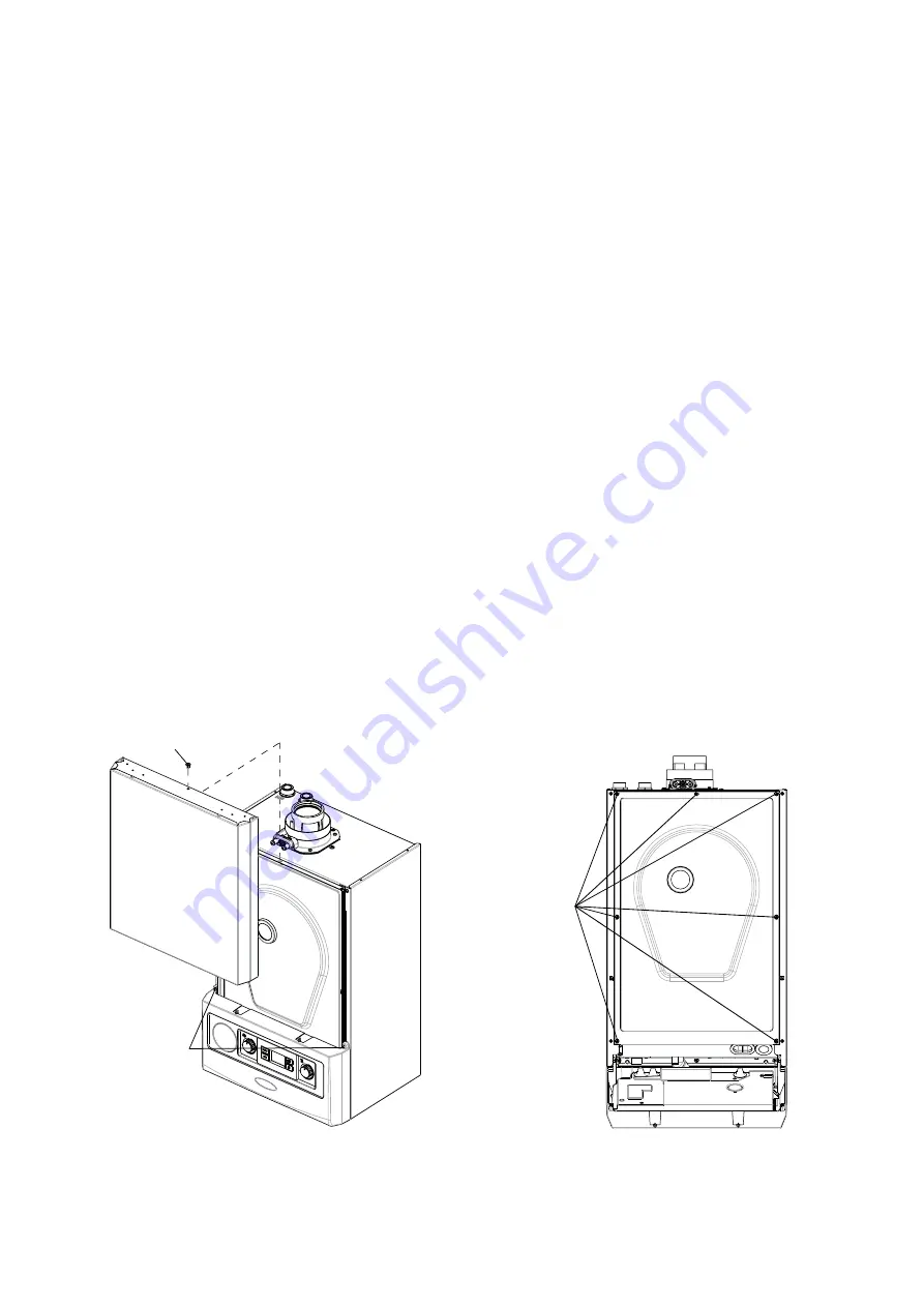
7.2 PREPARE FOR SERVICING - Fig. 7.1 and 7.2
1. Ensure the electrical supply is isolated and the gas supply is off.
2. Remove the screw at the top centre of the front panel, then lift it up and remove the panel. Release the two screws
securing the control panel and lower the panel.
3.
Remove the seven screws securing the room sealed chamber panel and remove the panel, taking care not to damage the
seal.
4. Remove the single screw securing the top of the air supply pipe and withdraw it from the fan connection.
5. Pull off the ignition lead from the electrode.
6. Remove the upper and lower spring clips from the gas supply pipe.
7. Remove the gas valve pressure tube from the fan inlet
8. Disconnect the fan wiring connector.
9. Remove the four 10 mm nuts securing the combustion manifold front assembly. See Fig. 7.4.
10. Withdraw the complete burner/fan/air inlet assembly towards you.
11. Remove the condensate trap assembly and clean as described in Section 8.11.
Fig. 7.1
Control panel
fixing screws
Case front panel
fixing screw
Room sealed panel
fixing screws (7)
Fig. 7.2


