26
Alpha InTec S - Commissioning
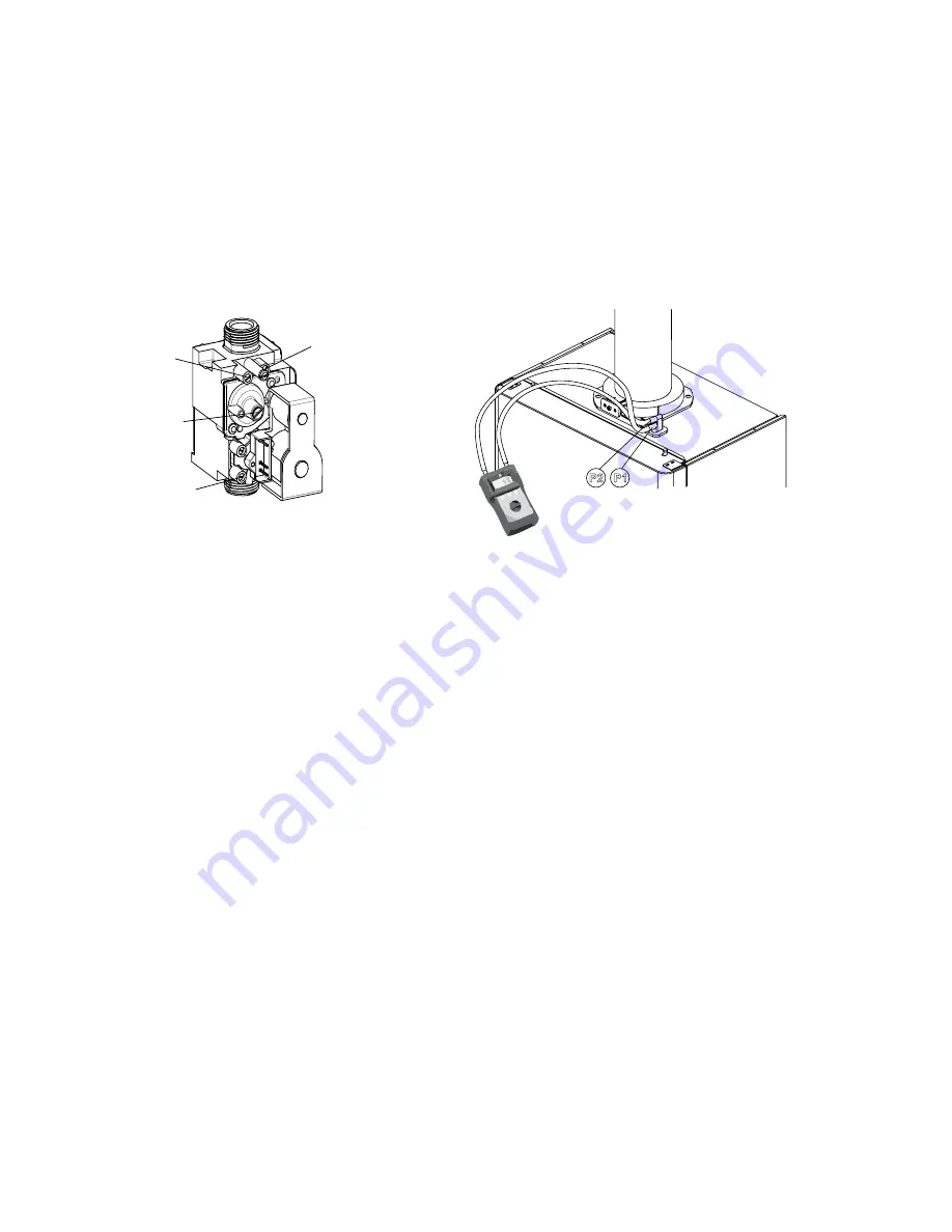
5.6 CHECK THE BURNER PRESSURES AND COMBUSTION - Figs. 27, 28
Press and hold in the reset button f
or eight seconds and the boiler will fire at a fix
ed output depending on the position of the
boiler central heating thermostat knob.
Turn the boiler central heating thermostat to maximum to check the maximum central heating burner pressure.
With the boiler central heating thermostat set to maximum fully open a hot tap to check the maximum domestic hot water
burner pressure. In this mode the inlet gas supply pressure and CO/CO
2
ratio can be checked.
Refer to Technical Data, Section 2.1 and 2.2 for the required differential burner pressure values.
Note:
The burner pressure settings have been factory set and should not require adjusting.
Combustion testing must be carried out by a competent person using a calibrated analyser conforming to BS EN 50379 part 3.
5.7 FINAL COMMISSIONING
1. Allow the heating system to heat up, then balance the system to achieve the necessary temperature difference across
the heating fl w and return pipes at the boiler and check the system volume and pressure. (Refer to Technical Data,
Sections 2.1, 2.2 and 2.3).
2. Turn off the boiler.
4. Thoroughly flush out the water pipework (refer to Section 3.9) and with no pressure in the boiler heating circuit, empty the
cyclone (if applicable) at it's drain point (see Fig. 13) of any debris.
5. Re-pressurise the system as described in Section 5.1.
5.8 FINAL ASSEMBLY
1. Raise the control panel and secure in position with the screws provided.
Note:
If the wall jig is used, fit the bottom t ay over the base of the boiler.
2. If the boiler is to be left in service with the User, set the controls, clock (if fitted, see User's Ope ating manual) and room
thermostat (if fitted) to the User's requirement .
3. If the boiler is not to be handed over immediately, close the boiler gas service cock and switch off the electrical supply.
4. If there is any possibility of the boiler being left during frost conditions, then the boiler and system should be drained
(refer to Section 7.2). It is recommended that a label is attached to the boiler drawing attention to the fact that the
system has been drained.
5. Complete the details of the installation in the Benchmark Checklist at the back of these instructions.
Fig. 27
Fig. 28
Max. CO
adjustment
2
Outlet
pressure
test point
Inlet
pressure
test point
Min. CO
adjustment
(under cap)
2
+
-
+
-
P1
P2


