33
7.10 GAS VALVE - Fig. 31
Note:
The replacement of the gas valve or PCB must be carried out by a Gas Safe registered engineer with the use of a flue
analyser.
1. Gain access behind the front casing as in Section 7.1.
2. Disconnect the positive pressure tube from the gas valve.
3. Disconnect the electrical plug.
4. Disconnect the burner manifold pipe union and the gas inlet pipe union.
5. Remove the two screws from beneath the boiler and lift out the valve assembly.
6. Lift out the gas valve.
7. Fit the new assembly and re-assemble in reverse order and test for gas tightness.
8. Light the boiler. (Refer to Commissioning, Section 5.4) and adjust the gas valve as described in the instructions supplied
with the replacement valve.
9. Complete re-assembly as described in Routine Servicing, Section 6.4 paragraphs 5 to 9.
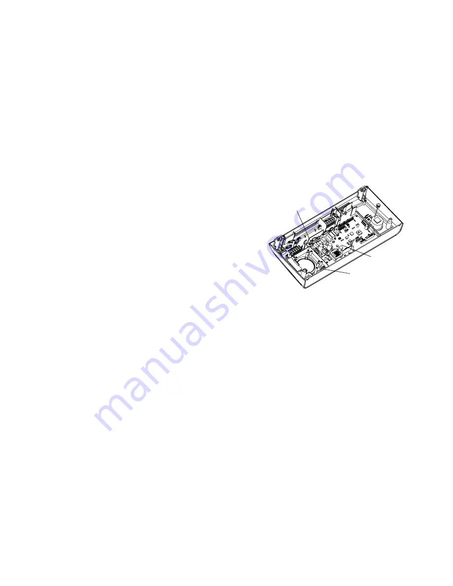
7.11 TERMINAL BLOCK FUSE - Fig. 32
The fuse is located on the PCB.
1. Gain access as described in Installation, Section 4.8.
2.
Lift out and remove the fuse. Fit a 3.15 AF fuse as a replacement.
Note:
A spare fuse is supplied, as shown in Fig. 32.
3. Re-assemble in reverse order.
7.12 PCB - Fig. 32
Note:
The replacement of the gas valve or PCB must be carried out by a
Gas Safe registered engineer with the use of a flue analyse .
1. Gain access behind the control panel as described in Section 7.1.
2. Disconnect all the wiring connectors from the PCB.
3. Remove the fi e fixing scr ws and carefully withdraw the board
from the switch spindles.
4. Re-assemble in reverse order. Refer to the wiring diagram in Section
8.1 for connections.
5. Light the boiler and adjust the PCB as described in the instructions supplied with the replacement PCB.
7.13 ALPHA CONTROLS (if fitted) - Fig 24
Note:
For replacement only use an Alpha two channel control.
Do not fit a single hannel control.
1. Gain access behind the control panel as described in Section 7.1.
2. Remove the three screws securing the terminal block cover at the rear of the panel.
3. Disconnect the wiring from the control.
4. Remove the three control retaining screws and withdraw the control from the panel.
5. Fit the new control, and connect the wires as follows:-
Brown wire to terminal 1, Blue wire to terminal 2, Black wire to terminal 3, Grey wire to terminal 4 and White wire to
terminal 5, (or as per the instructions supplied with the control).
6. Re-assemble in reverse order. Refer to the User's instructions and the boiler's control cover to set the control.
7.14 COMBUSTION CHAMBER INSULATION
Gain access to the combustion chamber as described in Section 8.1.
Front panel insulation - Fig. 30
1. Remove the electrodes from the combustion chamber front as described in Section 7.3.
2. Remove the four screws securing the burner.
3. Carefully remove the insulation.
Back panel insulation - Fig. 33
1. Remove the combustion chamber front/burner assembly.
2. Carefully remove the insulation, suction applied to the centre of the insulation will aid this.
Fit a new panel and re-assemble in reverse order.
Alpha InTec S - Component Replacement
Fig. 32
PCB
PCB fuse
Spare fuse


