35
Alpha InTec S - Component Replacement
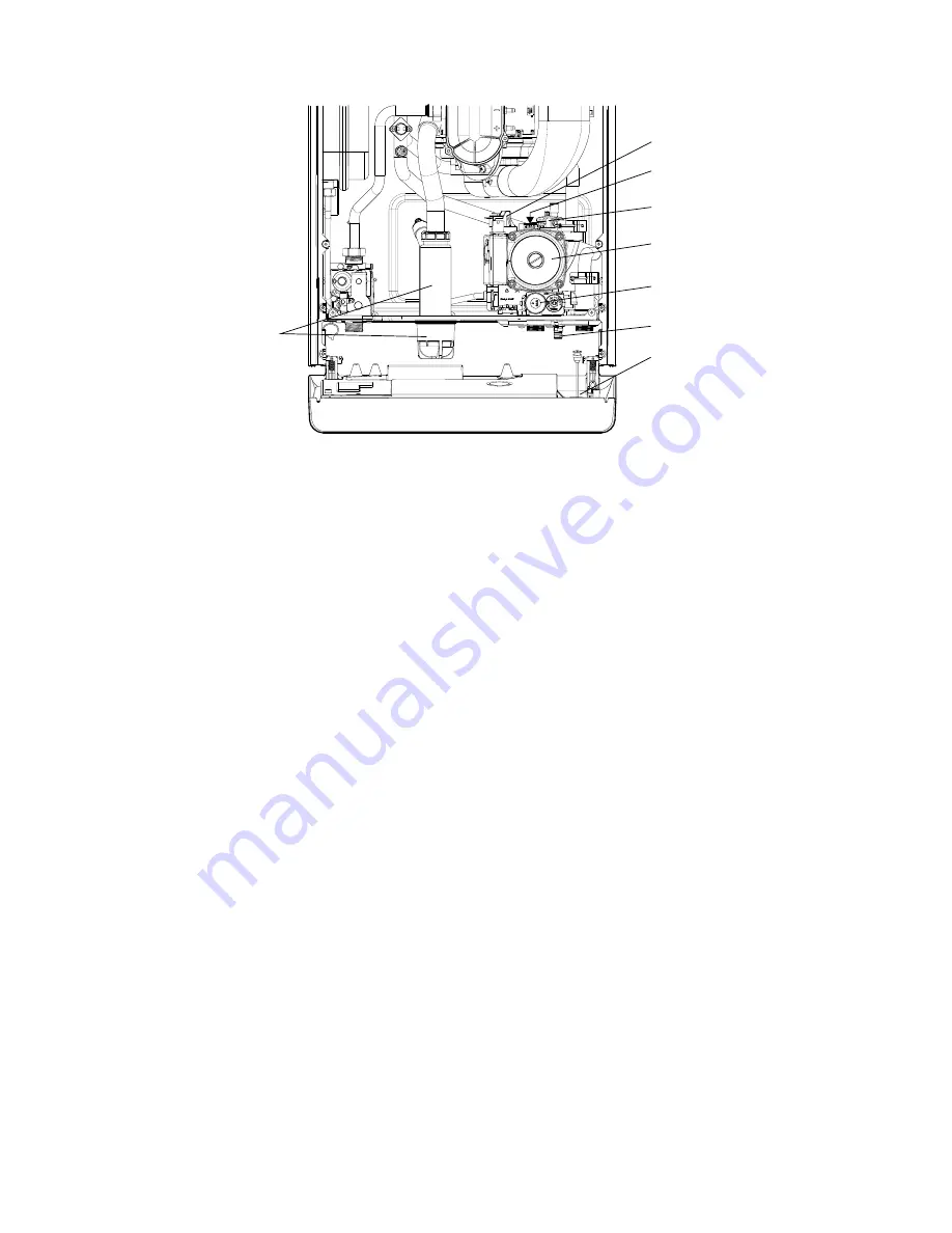
7.21 AUTOMATIC AIR VENT - Fig. 34
1. Gain access behind the front casing and drain the boiler heating circuit as described in Sections 7.1 and 7.2.
2. Turn the automatic air vent anticlockwise and lift it out
3. Insert the new air vent using a new washer and turn it clockwise to lock it in position.
4. Refill and pressu ise the system. (Refer to Commissioning, Section 5.1).
7.22 PUMP - Refer to Fig. 34
Gain access behind the front casing and drain the boiler heating circuit as described in Sections 7.1 and 7.2.
Pump head
1. Using a 4 mm Allen key remove the four socket head screws securing the pump head to the body. Withdraw the head
and disconnect the plug.
2. Connect the plug to the new head. Ensure the pump is set to maximum (3) and re-assemble in reverse order.
3. Refill and pressu ise the system. (Refer to Commissioning, Section 5.1).
7.23 PRIMARY PRESSURE SWITCH - Fig. 34
1. Gain access behind the front casing and drain the boiler heating circuit as described in Sections 7.1 and 7.2.
2. Disconnect the wiring from the pressure switch.
3. Withdraw the retaining clip on the left side of the switch and lift the switch upwards to remove.
4. Insert a new switch and re-assemble in reverse order.
When connecting the wiring to the new switch the polarity of the wires is not important.
7.24 PRESSURE RELIEF VALVE - Fig. 34
1. Gain access behind the front casing and drain the boiler heating circuit as described in Sections 7.1 and 7.2.
2. Disconnect the pressure relief valve outlet fitting
3. Remove the two screws securing the expansion relief valve and the left hand DHW manifold securing screw.
4. Withdraw the retaining clip from the valve and pull the valve from the pump housing.
5. Re-assemble in reverse order.
6. Refill and pressu ise the system. (Refer to Commissioning, Section 5.1).
Fig. 34
Primary pressure switch
Automatic air vent
Pump
Pressure relief valve
Pressure gauge
Drain point
Pressure gauge sensor position
Condensate trap


