18
C048-740-30 R02, Rev. C (01/2020)
4.8.1
4.8.1 Return Bus Interconnection Jumper Installation
Return Bus Interconnection Jumper Installation
(Models with Internal RTN)
(Models with Internal RTN)
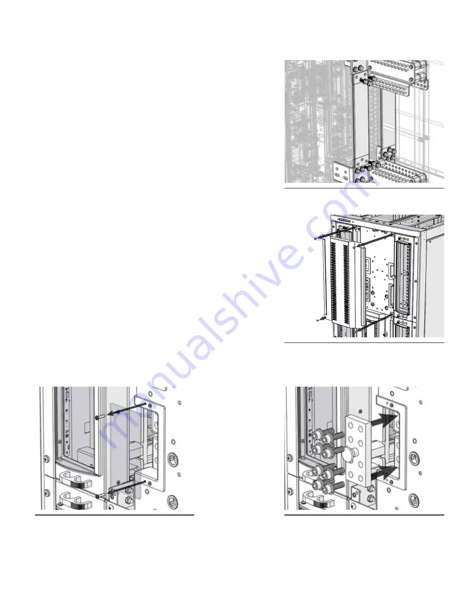
Step 1.
Depending on the selected configuration, align the return
jumper in place between the return buses.
Step 2.
For each return jumper, insert the six 3/8 in. bolts with flat and
lock washers through the pems located on the return buses.
Take caution as to not drop any hardware during this process
(see Figure 34).
Step 3.
Ensure that each jumper is straight and parallel with the
return buses, then tighten all hardware.
4.8.2
4.8.2 Hot Bus Interconnection Jumper Installation
Hot Bus Interconnection Jumper Installation
Step 1.
Remove the center panel by loosening the four pan head
screws (see Figure 35).
Step 2.
Remove the hot jumper access panel by removing the two
#6-32 screws (see Figure 36).
Step 3.
Firmly holding onto the plastic handle, carefully insert the hot
jumper into the hot jumper access compartment and align it
with the hot buses.
Step 4.
Insert the eight 3/8 in. socket cap bolts with flat and lock
washers through the hot jumper and into the pems of the hot
buses. Take caution as to not drop any hardware during this
process (see Figure 37).
Step 5.
Ensure that each jumper is straight and parallel with the hot
buses, then tighten all hardware.
Step 6.
Reattach the hot jumper access panel and the center panel.
Figure 34. RTN Jumper
Figure 35. Center Panel
Figure 36. HOT Jumper Access Panel
Figure 37. HOT Jumper
Summary of Contents for PowerBay BDFB
Page 51: ......


