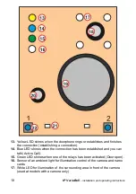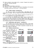
IP VarioBell
- installation and operating instructions
25
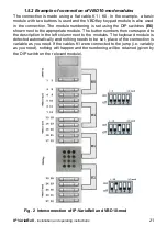
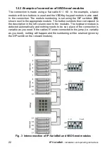
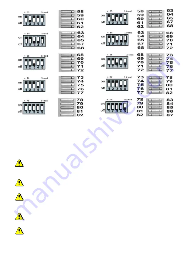
The modules are numbered in the figure above, on the left side there are
modules with 5 call buttons VBD5-mod and on the right side there are modules
with 10 call buttons VBD10-mod.
The module with the desired numbering can be found in the figure above
and on the left side of it there is a combination of the DIP switch
(E6)
you have
to set on this module.
To set the number of call buttons (number of phonebook entries)
correctly, you need to set the number of connected call buttons in the menu of
the doorphone
The numbering is independent of the order of connection of the call button
modules with K1 cables
If you connect to the system two call button modules with the same DIP
switch setting, nothing will happen, but both modules will have the same call
button numbers and therefore the same function.
For Keyboard module, you need to set the keyboard presence in the
menu settings (the phonebook will expand to 999 entries)
If you connect two keyboards to the system, they will both function and
perform the same function.
Summary of Contents for IP-VarioBell IPVB-00
Page 2: ...Installation and operating instructions ...
Page 3: ...IP VarioBell User instructions 3 ...
Page 17: ...IP VarioBell installation and operating instructions 17 ...
Page 24: ...IP VarioBell installation and operating instructions 24 ...
Page 28: ...IP VarioBell installation and operating instructions 28 2 Installation 2 1 Assembly ...
Page 32: ...IP VarioBell installation and operating instructions 32 ...
Page 89: ......
Page 91: ... Alphatech Technologies s r o 2014 2016 version V3 5 ...


