background image

14

Summary of Contents for NVE-N852A

Page 1: ...zano Sul Naviglio MI Italy Tel 02 48 47 81 ALPINE ELECTRONICS FRANCE S A R L RCS PONTOISE B 338 101 280 98 Rue De La Belle Etoile Z I Paris Nord Il B P 50016 F 95945 Roissy Charles De Gaulle Cedex Fra...

Page 2: ...brake pedals etc can be extremely hazardous DO NOT SPLICE INTO ELECTRICAL CABLES Never cut away cable insulation to supply power to other equipment Doing so will exceed the current carrying capacity o...

Page 3: ...tal cover is located Route the Speed Pulse Sensor cable away from the audio cables in order to avoid picking up noises Caution HAVE THE WIRING AND INSTALLATION DONE BY EXPERTS The wiring and installat...

Page 4: ...t of silicone or some double stick tape applied to the bottom of the antenna This will prevent the magnetic base from moving and possibly scratching the paint on the vehicle Before Installing the Syst...

Page 5: ...his process with checking the tachometer wire The tach wire increases voltage with the engine s RPM The speed pulse wire increases voltage with the vehicle s actual speed If any of these condi tions d...

Page 6: ...itself If the vehicle icon does not move smoothly as you drive or the street name does not appear on the bottom of the screen you may not have the proper VSS wire Double check your connections and ver...

Page 7: ...he roof Clean dust and oil at the mounting location and mount the antenna Notes The magnet of the antenna is very strong Proceed cautiously to prevent any damage to the vehicle s body Keep the magnet...

Page 8: ...control computer etc in this case contents of the computer memory may be erased when the battery lead is disconnected Water proof pad 6 1 Connect the power lead to this unit Insert until a click sound...

Page 9: ...parking brake signal line Connect to a metal part of chassis body with screw To the vehicle speed pulse line Use this to connect a device having the IN INT function Use this to connect a device having...

Page 10: ...adhesive on the Velcro strips Press the Navigation unit onto the mounting location Continued to 5 Securing leads etc a When mounting on the rear tray Mount the brackets 1 on the unit Mount the bracket...

Page 11: ...the floor with flanged self tapping screws M5 15 5 and spring washers M6 6 Warning Do not damage pipe or wiring when drilling holes Continued to 5 Securing leads etc 5 6 a When mounting with floor ba...

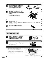
Page 12: ...he engine key Make sure the unit is operating correctly by referring to the Owner s Manual ON Make sure all factory components such as brake lamps parking lamps etc work correctly a Remote control hol...

Page 13: ...13...

Page 14: ...14...

Page 15: ...15...

Reviews: