18
Alpine TR42 Direct Vent Gas Fireplace
VENTING
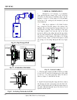
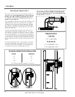
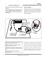
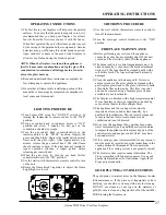
Fig. 13– Termination Orientation
HOT
Wall Penetration
Heat Shield
Make Sure Arrow
is pointing up.
Fig. 12– Pipe Through Wall
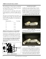
Fig.14– Anchoring Termination to Wall
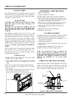
VERTICAL TERMINATION
1.
Maintain the 1-1/2” clearances to combustibles
when passing through ceilings, walls, roofs, enclosures,
attic rafters, or other nearby combustible surfaces. See the
diagrams on page 13 of this manual for the maximum
vertical rise of the venting and the maximum horizontal
offset limitations.
2.
With the gas appliance in its desired location,
drop a plumb bob from the ceiling to the position of the
appliance flue exit and mark the location where the vent
will penetrate the ceiling. Drill a small hole at this point.
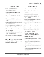
Next, drop a plumb bob from the roof to the hole
previously drilled in the ceiling and mark the spot where
the vent will penetrate the roof. Determine if ceiling joists,
roof rafters, or other framing will obstruct the venting
system. You may choose to relocate the fireplace or offset
the venting to avoid cutting framing members (see figure
16).
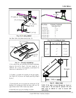
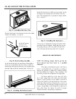
F i r e s t o p
F l a s h i n g
Fig. 15– Vertical Venting
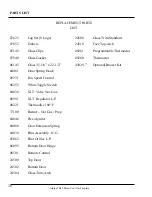
3. A Firestop spacer must be installed in the floor or ceiling
of every level. To install the Firestop spacer in a flat ceiling
or wall, cut a 10 inch square hole. Frame the hole as
shown in (Figure 17) and install the firestop.
4. Assemble the desired lengths of pipe and elbows. Ensure
that all pipes and elbow connections are in the fully twist–
locked position and sealed with Mill-pac brand sealant on
the inside collar and aluminum tape on the exterior. An air
tight seal must be created.
FIRESTOP


