background image

10

-EN

Watching playback of 
external component

You can connect up to 2 external video 
components to the TV tuner unit.

To watch the playback, first follow steps 
1 and 2 on page 7, then perform the fol-
lowing steps.

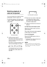
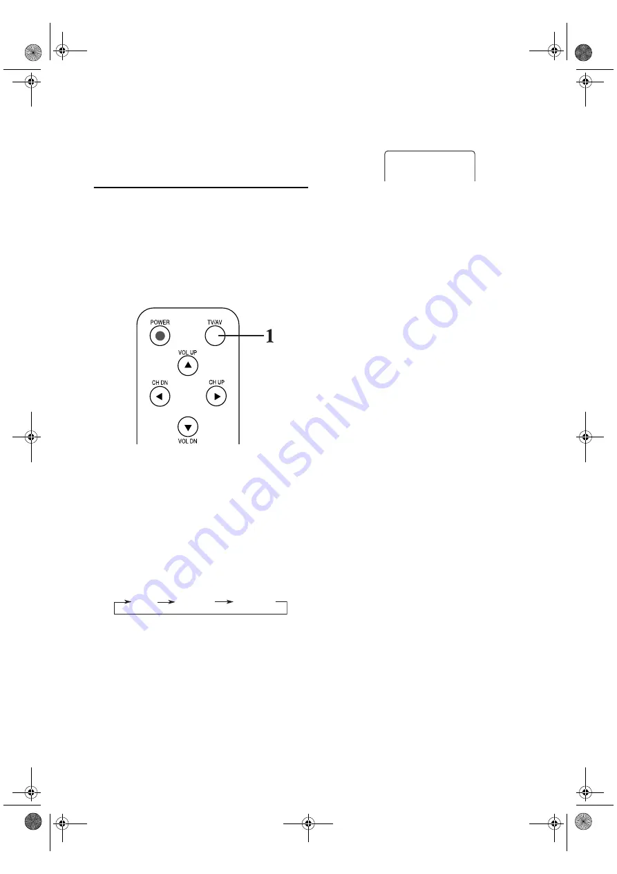
1

Select the input source.

Press the TV/AV button on the re-
mote controller to select the input 
source you want.

Each time you press the button, the 
input source changes as follows:

The selected input source name 
also appears on the screen for 3 
seconds.

2

Play back the external component.

To operate the external compo-
nents, refer to the manuals of the 
connected components.

3

Adjust the volume level on the car 
receiver.

To check the current input source

Press the CH CALL button on the re-
mote controller.

The current input source name appears 
on the screen for 3 seconds.

To turn off the power

Press the POWER button on the re-
mote controller.

• Turning off the engine will also turn 

off the TV tuner system.

NOTES

• When you watch the screen aslant, the picture 

might not be clear. This is not a malfunction. The 
finest picture can be seen when you watch the 
screen straight.

Remote controller

AUX1

TV

AUX2

AUX1

Ex: When AUX1 is selected

TUE-T112P.book  Page 10  Friday, April 29, 2005  11:40 AM

Summary of Contents for TUE-T112P

Page 1: ...A INC Suite 203 7300 Warden Ave Markham Ontario L3R 9Z6 Canada Tel 1 800 ALPINE 1 1 800 257 4631 ALPINE ELECTRONICS OF AUSTRALIA PTY LTD 6 8 Fiveways Boulevarde Keysborough Victoria 3173 Australia Tel...

Page 2: ...auto memory 8 Setting the channel selection 9 Watching playback of external component 10 Adjusting the headphone volume 11 Maintenance Information In Case of Difficulty 13 Specifications 14 Installati...

Page 3: ...swallowed consult a physician immediately USE THE CORRECT AMPERE RATING WHEN RE PLACING FUSES Failure to do so may result in fire or electric shock CAUTION HALT USE IMMEDIATELY IF A PROBLEM APPEARS Fa...

Page 4: ...nce carefully check all electrical connections for shorted circuitry Also have your vehicle s voltage regulator checked Maintenance If you have problems do not attempt to repair the unit yourself Retu...

Page 5: ...for con necting the diversity antenna B INPUT 2 jacks VIDEO AUDIO L AUDIO R C INPUT 1 jacks VIDEO AUDIO L AUDIO R D POWER SUPPLY connector E REMOTE EYE INPUT F OUTPUT jacks VIDEO AUDIO L AUDIO R G HEA...

Page 6: ...7 8 9 10 G CH UP Channel up button 7 H CH DN Channel down button 7 I CH CALL button 10 Before using the remote controller Aim the remote controller directly at the remote sensor on the color mon itor...

Page 7: ...ction 3 Closing the cover Slide the cover as illustrated until a click is heard WARNING Battery type CR2025 battery or equivalent WARNING DO NOT OPERATE ANY FUNCTION THAT TAKES YOUR ATTENTION AWAY FRO...

Page 8: ...set to AUTO See page 9 You can select only the channels preset by the auto memory func tion See page 8 If the channel selection is set to MANUAL See page 9 You can select all the channels Channel cove...

Page 9: ...mote controller The auto memory function starts and TV broadcast signals are picked up and stored in memory while scanning When scanning is over the screen shows the TV program of the smallest channel...

Page 10: ...re mote controller repeatedly to select TV 2 Set the channel selection to AUTO or MANUAL Press the SEEK button on the re mote controller Each time you press the button the channel selection alternates...

Page 11: ...t To operate the external compo nents refer to the manuals of the connected components 3 Adjust the volume level on the car receiver To check the current input source Press the CH CALL button on the r...

Page 12: ...st the volume level be tween 0 and 35 The headphone volume level appears on the screen NOTE This adjustment is only for the connected head phones but not for the speakers in the car When ad justing th...

Page 13: ...oducts for long periods of time Do not use cleansers which have polishing granules because this could damage the surface of the unit Clean dirt by wiping lightly with a soft cloth When the unit is ver...

Page 14: ...be No picture obtained Mode switch is not set to a desired mode Select desired mode by pressing TV NAV VIDEO button Temperature inside car is high Lower the temperature Poor connections between monito...

Page 15: ...rea setup menu screen does not come out Press the button after changing TV band to TV1 or TV2 It cannot be operated if it is TV3 TV area cannot be changed Even if trying to change the TV area it stays...

Page 16: ...DIVERSITY ANTENNA Output impedance 75 ohms 3 5 mini jack Operating Voltage DC14 4V 11 to 16V Operating Current 50mA Operating Temperature Range 10 C 60 C TUE T112P book Page 15 Friday April 29 2005 11...

Page 17: ...onsult a physician immediately DO NOT INSTALL IN LOCATIONS WHICH MIGHT HINDER VEHICLE OPERATION SUCH AS THE STEERING WHEEL OR GEARSHIFT Doing so may obstruct forward vision or hamper movement etc and...

Page 18: ...The diversity antenna supplied with this unit is designed specifically for use with the ALPINE mobile color monitor system It cannot be con nected to the car radio Do not rub the antenna or the anten...

Page 19: ...emote EYE INPUT POWER SUPPLY AUDIO Monitor etc Headphone not supplied Ground wire Connected to metal section on the vehicle Antenna element Loading section Antenna base Ground wire Connected to metal...

Page 20: ...enna element s end to the location where it does not overlap with a heating wire or glass antenna When the attachment surface over laps with an electrode Attach the antenna to either the left or right...

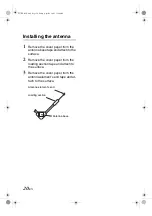
Page 21: ...h to the surface 2 Remove the cover paper from the loading section tape and attach to the surface 3 Remove the cover paper from the antenna element s end tape and at tach to the surface Antenna elemen...

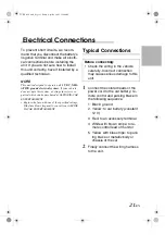
Page 22: ...he fuse with one of the specified ratings If the fuse blows frequently consult your ALPINE IN CAR ENTERTAINMENT Typical Connections 1 Connect the colored leads of the power cord to the car battery re...

Page 23: ...blue stripe Fuse block Ignition switch To parking brake or metallic body or chassis of the car To remote control lead of monitor To an accessory terminal in the fuse block Yellow 1 To a live terminal...

Page 24: ...cannot be turned on Is the red lead connected Picture does not come on screen Is the parking brake engaged Is the yellow blue striped cord correctly connect ed Picture does not appear clearly Is the c...

Reviews: