Rot = Regler fordert Wärme an
Grün = Energiesparberieb (Nachtabsenkung)
4. Anzeigen
5. Technische Daten
5. Technical data
6. Zubehör
6. Accessories
Betriebsspannung:
230V~ / 50Hz
Regelbereich:
10 … 50ºC
Schaltdifferenz:
ca. 1K
Leistungsaufnahme:
ca. 1VA
Temperaturabsenkung:
ca. 5K fest (Anschluss L1 an )
Kontakt:
Schließer 230V~ max.16(2)A
Externer Fühler:
2k
Ω
NTC entspr. DIN 44574
(doppelt isoliert) entspr. DIN EN 60730-2-1
Fühlerbrucherkennung:
Heizung wird abgeschaltet
Anzeigen:
LED für Heizen rot, für Nachtabsenkung grün
Schraubklemmen:
0,5 – 2,5 mm
2
Befestigung:
in UP-Dose Ø 55 mm
Wirkungsweise:
Typ 1.C
Verschmutzungsgrad: 2
Bemessungsstoßspannung: 4000V
Schutzart:
IP30
Schutzklasse:
Nach sachgemäßer Montage werden die Anforderungen
der Schutzklasse II erfüllt.
Umgebungstemperatur:
0 … 40ºC
Lagertemperatur:
-20 … +70ºC
Temperatur der Kugeldruckprüfung: 75°C
Operating range:
230V~ / 50Hz
Control range:
10 … 50ºC
Switching difference:
approx. 1K
Power consumption:
approx. 1VA
Temperature decrease:
approx. 5K (fixed); (connection of L1 to )
Contact:
make contact, max. 230V~, max.16(2)A
External sensor (double-insulated):
2k
Ω
, NTC acc. to. DIN 44574
in compliance with DIN EN 60730-2-1
Sensor breakdown detection:
heating is turned off
Indicators:
red LED for “heating” and green LED
for “night decrease mode”
Terminal screws:
screw terminals (0.5 … 2.5 mm
2
)
Mounting:
in an UP box (Ø 55 mm)
Mode de fonctionnement:
type 1.C
Degré de pollution:
2
Tension nominale d’impulsion:
4000V
Degree of protection:
IP30
Protection class:
The requirements of the protection class II will be
met after correct installation.
Ambient temperature:
0 … 40ºC
Storage temperature:
-20 … +70ºC
Temperature of ball indentation test: 75°C
– Ersatzfühler HF-8/4-K2
– THF – Schutzhülse bei Estrichmontage des Fühlers, passend für Leerrohr Ø 20 mm
– Spare sensor HF-8/4-K2
– Protecting sleeve, type THF, for the installation of the sensor into the pavement
(inside a suitable empty conduit, Ø 20 mm)
Red = controller requests heat supply
Green = energy economizing mode (night temperature decrease mode)
4. Indicators
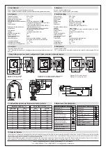
8. Fühlerkennwerte / Sensor characteristics
9. Verwendete Symbole / Explanation of symbols
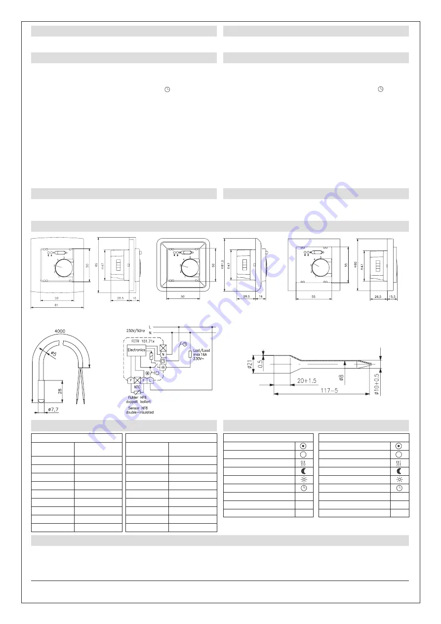
7. Maßzeichnungen und Anschluss-Schaltbilder / Dimensioned drawings and connection diagrams
Die angegebenen technischen Daten wurden durch uns jeweils in einem dafür geeigneten Prüf- und Testumfeld (hierzu geben wir auf Anfrage Auskunft) ermittelt und stellen nur auf dieser Grundlage
die vereinbarte Beschaffenheit dar. Die Prüfung der Eignung für den vom Auftraggeber / Kunden vorgesehenen Verwendungszweck oder den Einsatz unter den konkreten Gebrauchsbedingungen ob-
liegt dem Auftraggeber / Kunden; hierfür übernehmen wir keine Gewährleistung. Änderungen vorbehalten.
We determined the technical data provided in an inspection and test environment suited to this task (we are happy to provide details on request) and this data only presents the agreed properties on
this basis. The purchaser / customer is responsible for checking the suitability of the use or usage intended by the purchaser / customer under the specific conditions of use; we do not accept any liabili-
ty for this. We reserve the right to amendments.
ALRE-IT Regeltechnik GmbH · Richard-Tauber-Damm 10 · D-12277 Berlin
Tel.: +49(0)30/399 84-0 · Fax: +49(0)30/391 70 05 · mail@alre.de · www.alre.de
10. Gewährleistung / Warranty
Table of sensor characteristics NTC 2k
Sensor Resistance
temperature [°C]
value [k
Ω
]
0
5.642
10
3.657
15
2.973
20
2.431
25
2.000
30
1.654
40
1.151
50
0.816
60
0.590
Fühlerwerttabelle NTC 2k
Fühler- Wider-
temperatur [°C]
standswert [k
Ω
]
0
5,642
10
3,657
15
2,973
20
2,431
25
2,000
30
1,654
40
1,151
50
0,816
60
0,590
Regler 50 x 50 mit Alre-Rahmen
Controller (50 x 50) with Alre type frame
Regler 50 x 50 mit Beispiel-Rahmen und Zwischenrahmen
Controller (50 x 50) with sample frame and intermediate frame
Regler 55 x 55 mit Beispiel-Rahmen
Controller (55 x 55) with sample frame
Bedien- und Anzeigesymbole
Regelung EIN
Regelung AUS
Heizung EIN
Nachtabsenkung EIN
Anschluss Heizung
Anschluss Temperaturabsenkung
Anschluss Phase
L
Anschluss Neutralleiter
N
Anschluss Fühler
F
Operating and display symbols
Control ON
Control OFF
Heating ON
Night decrease ON
Heating connection
Connection Temperature decrease
Phase connection
L
Neutral conductor connection
N
Sensor connection
F

