background image

Stand 11.2013

1

5 21 719 02

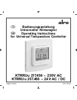
KTRRUu 217.456 – 230 V AC

KTRRUu 257.456 – 24 V AC / DC

Bedienungsanleitung

Universeller Klimaregler

Operating Instructions

for Universal Temperature Controller

D

GB

Summary of Contents for KTRRUu 217.456

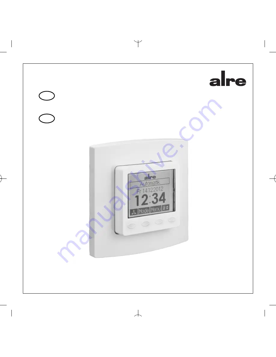
Page 1: ...Stand11 2013 1 5 21 719 02 KTRRUu 217 456 230V AC KTRRUu 257 456 24V AC DC Bedienungsanleitung Universeller Klimaregler Operating Instructions for Universal Temperature Controller D GB...

Page 2: ...Technische Daten 24V AC DC Version KTRRUu 257 456 23 11 Ma zeichnung 25 12 F hlerfehler Notbetrieb 26 13 Zubeh r 26 14 Gew hrleistung 26 bersicht Bedienungsanleitung Dieses Ger t darf nur durch eine...

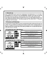
Page 3: ...Version 2 Anwendung Das Ger t besitzt 4 Sensortastfl chen die durch die gepr gten Symbole gekennzeichnet sind Ihre Funktion kann sich abh ngig von der Bedienung ver ndern und wird jeweils im Display o...

Page 4: ...bzw beendet wird oder das Expertenmen auf gerufen wird Die tempor re Solltemperatur einstellung erfolgt bei den Reglertypen Heizen Heizen K hlen und K hlen ber die gleichen Tasten 4 2 Einstellung L ft...

Page 5: ...ung einer Temperatur von ca 5 C am internen F hler bzw am aktivierten externen F hler die Frostschutzfunktion ausgel st Dabei wird im 2 Rohr Betrieb der gemeinsame Heiz K hlausgang O1 aktiv Es wird da...

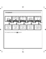
Page 6: ...6 5 Hauptmen Das Hauptmen wird mit Taste beendet Untermen Party siehe 5 1 Untermen Urlaub siehe 5 2 Untermen Uhrzeit siehe 5 3 Untermen Datum siehe 5 3 Untermen Temperatur siehe 5 4...

Page 7: ...men Einstellungen siehe 5 7 Aufruf Expertenmen siehe 6 Ist der Regler als Heizen K hlen Regler konfiguriert siehe 6 2 k nnen separate Tagesprogramme f r den Heizbetrieb und K hlbetrieb erstellt werden...

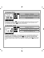
Page 8: ...ge Betriebsart Die Partyfunktion kann durch Bet tigung der Tastfl che jederzeit beendet werden 5 2 Untermen Urlaub Die Eingaben Tag Urlaubsbeginn Monat Urlaubsende und Tag Urlaubsende erfolgen analog...

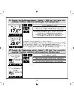
Page 9: ...s Datums Jahr Monat Tag erfolgt analog zur Eingabe der Uhrzeit Stunde 1 Abbruch der Eingabe R ckkehr ins Hauptmen Wechsel zu Eingabe Minute Komfort Temperatur 0 5K Abbruch der Eingabe R ckkehr ins Hau...

Page 10: ...urwert K hlen 1K Auf diese Temperatur wird w hrend der ECO Zeiten geregelt ECO Temperatur 0 5K Abbruch der Eingabe R ckkehr ins Hauptmen Bei Eingabe ECO Temperatur Heizen und aktivierter K hlfunktion...

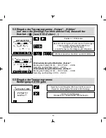
Page 11: ...n Montag bis Freitag 00 00 9 00 16 00 00 00 Samstag und Sonntag 00 00 24 00 Position 15 Minuten Beenden der Eingabe Wurden keine nderungen vorgenommen erfolgt eine R ckkehr zur Auswahl des Wochentags...

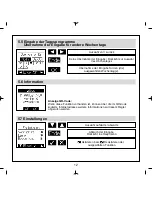
Page 12: ...hme der Eingabe f r den die ausgew hlten Wochentag e 5 6 Information Anzeige QR Code Wenn diese Funktion vorhanden ist k nnen ber die im QR Code kodierte Internetadresse weitere Informationen zu diese...

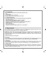
Page 13: ...langen Stillstandszeiten Bei Warmwasserheizungen wird die Aktivierung des Ventilschutzes empfohlen Ist der Ventil und Pumpenschutz aktiviert steuert der Regler montags 11 00 Uhr das Ventil und oder ei...

Page 14: ...aufgerufen Achtung In diesem Men werden Regelungseinstellungen vorgenommen die nur durch eine quali fizierte Heizungs oder Elektrofachkraft durchgef hrt werden d rfen Einstellungen im Expertenmodus k...

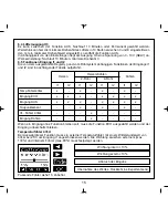
Page 15: ...1 und I2 sind in nachfolgender Tabelle aufgef hrt I1 I2 I1 I2 I1 I2 I1 I2 Temp F hler 47k x x x x Eingang ECO x x x x x x x Eingang AUS x x x x x x x Taupunktsensor x x x VL F hler 47k x Eingang K hle...

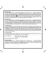
Page 16: ...Zustand Die Wirkweise des Eingangs kann an den Kontakt angepasst werden siehe 6 7 Taupunktsensor Die aktive K hlung kann bei Kondensatbildung durch einen optionalen externen Sensor unterbrochen werden...

Page 17: ...rch werden die an diesem Ausgang angeschlossenen Regler siehe 9 Anschluss Schaltbild 230V AC Version bzw 10 Anschluss Schaltbild 24V AC DC Version in den ECO Modus versetzt siehe 2 In der Betriebsart...

Page 18: ...6 8 Messkorrektur Der gemessene Temperaturwert kann f r den internen sowie den externen Temperaturf hler am Eingang I1 einzeln in Abh ngigkeit der Konfiguration im Bereich von 5K bis 5K in 0 1K Schri...

Page 19: ...abschalten 24V AC DC Version KTRRUu 257 456 Achtung vor Installation Versorgungsspannung abschalten Der elektrische Anschluss erfolgt gem Anschluss Schaltbild Punkt 9 230V AC Version bzw 10 24V AC DC...

Page 20: ...20 9 Anschlussschaltbild 230V AC Version KTRRUu 217 456...

Page 21: ...g und der F hler bzw L fterleitungen sind durch Setzen je eines Kabelbinders gegen Verlagerung zu sichern Hierbei ist auf einen m glichst kurzen Abstand maximal jedoch 15 mm zwischen Kabelbinder und N...

Page 22: ...altdifferenz 1K Anzeige beleuchtetes grafisches Display Elektrischer Anschluss Schraub Steckklemmen netzspannungsseitig 0 75 2 5 mm2 niederspannungsseitig 0 08 1 5 mm2 Leistungsaufnahme max 1W ca 2 2...

Page 23: ...23 10 Anschlussschaltbild 24V AC DC Version KTRRUu 257 456...

Page 24: ...hlen Schaltdifferenz 1K Anzeige beleuchtetes grafisches Display Elektrischer Anschluss Schraub Steckklemmen Versorgungsspannung u Schaltausg nge 0 75 2 5 mm2 F hler Kontakteingangsseitig L fterausgan...

Page 25: ...25 11 Ma zeichnung...

Page 26: ...S 3 externe Temperaturf hler PFC47 Strahlungsf hler als Pendelf hler STF 2 Strahlungsf hler im Raumf hlergeh use BTF2 C47 0000 Raumf hler ALF 2 Anlegef hler LF 22 Luftf hler HF 2 H lsenf hler F hlerwe...

Page 27: ...27...

Page 28: ...ed drawing 51 12 Sensor faults emergency operation 51 13 Accessories 51 14 Warranty 52 Table of contents overview Expert electricians only may open this device in due compliance with the wiring diagra...

Page 29: ...10 Connection diagram of the 24V AC DC model 2 Application functional description The device is equipped with 4 touch keys all of which have been marked by the symbol The func tions allocated to them...

Page 30: ...clock The same applies if the holiday or party function has been started or cancelled or the experts menu been called up With all controller types i e heating heating cooling or cooling controllers t...

Page 31: ...re value measured by the internal or the activated external sensor falls below a level of approx 5 C When controlling 2 pipe systems the common heating cooling output O1 is being activated The heating...

Page 32: ...32 5 Main menu Actuating the key terminates the main menu Submenu Party see 5 1 Submenu Holiday see 5 2 Submenu Time see 5 3 Submenu Date see 5 3 Submenu Temperature siehe 5 4...

Page 33: ...alling of the experts menu see 6 If the controller has been configured for heating cooling control applications see 6 2 separate weekday programs for both heating and cooling mode control operations c...

Page 34: ...opera tion in the previous mode Actuating the touch key cancels the party function at any time 5 2 Submenu Holiday The settings Day on which holidays begin Month in which holidays end and Day on which...

Page 35: ...d in the same manner as explained before with regard to the entry of the time Hour 1 Returning to main menu without saving entered data Changing to the minute entry display Comfort temperature 0 5K Re...

Page 36: ...tions are adjusted to these temperatures ECO temperature 0 5K Returning to main menu without saving entered data When entering the heating ECO temperature with the cooling function activated the syste...

Page 37: ...00 a m 16 00 00 00 p m Saturday and Sunday 00 00 24 00 p m Position 15 minutes Termination of entries If no changes have been made the system returns to the display for the selection of the weekday O...

Page 38: ...tered data Confirm settings with respect to the selected weekday s 5 6 Information Indication of the QR code The internet address coded in the QR code allows to access further information on this cont...

Page 39: ...tems activating the valve protection function is recommended After activation of the valve and pump pro tection function the controller actuates the valve s or triggers a heating pump once every Monda...

Page 40: ...m the main menu enables to call the experts menu Caution This menu enab les to make control settings that may only be performed by a qualified heating specialist or an expert electrician The settings...

Page 41: ...x x ECO input x x x x x x x OFF input x x x x x x x Dew point sensor x x x FLOW sensor 47k x Cooling input x Selecting the ECO function and leaving it unwired allocates no function to this input Heati...

Page 42: ...tional external sensor enables to interrupt the active cooling procedure in the event of conden sate formation The dew point sensor should be installed as close as possible to the place within the coo...

Page 43: ...ng The con trollers connected to this output see section 9 Connection diagram of the 230V AC model or sec tion 10 Connection diagram of the 24V AC DC model are thus initiated to operate in ECO mode se...

Page 44: ...method Two point method hysteresis control Factory preset specially suited for use with all temperature equalization systems PI PWM method PI proportional integral With all slow acting temperature eq...

Page 45: ...l KTRRUu 257 456 Prior to performing any installation works always make sure to switch off the power supply The electrical connection is to be realised as shown in the connection diagram in section 9...

Page 46: ...46 9 Connection diagram of the 230V AC model KTRRUu 217 456...

Page 47: ...sensors and fans should be protected against shifting by fixing one cable tie each as shown here below In doing so care must be taken to ensure that the distance between the cable tie and the mains v...

Page 48: ...48 10 Connection diagram and dimensioned drawing of the 24V AC DC model KTRRUu 257 456...

Page 49: ...play graphic display backlit Electrical connection pluggable screw terminals 0 75 2 5 mm2 supply voltage and switching outputs 0 08 1 5 mm2 on the fan contact input side fan output Power consumption a...

Page 50: ...50 11 Dimensioned drawing...

Page 51: ...cy mode FLOW sensor defective operation in heating mode no cooling takes place On condition that the actually adjusted operating mode allows to do so a relative duty cycle of 30 is being maintained to...

Page 52: ...only be warranted to this extent The testing with regard to the qualification and suitability for the client s intended application or the use under service conditions shall be the client s own duty W...

Reviews: