2
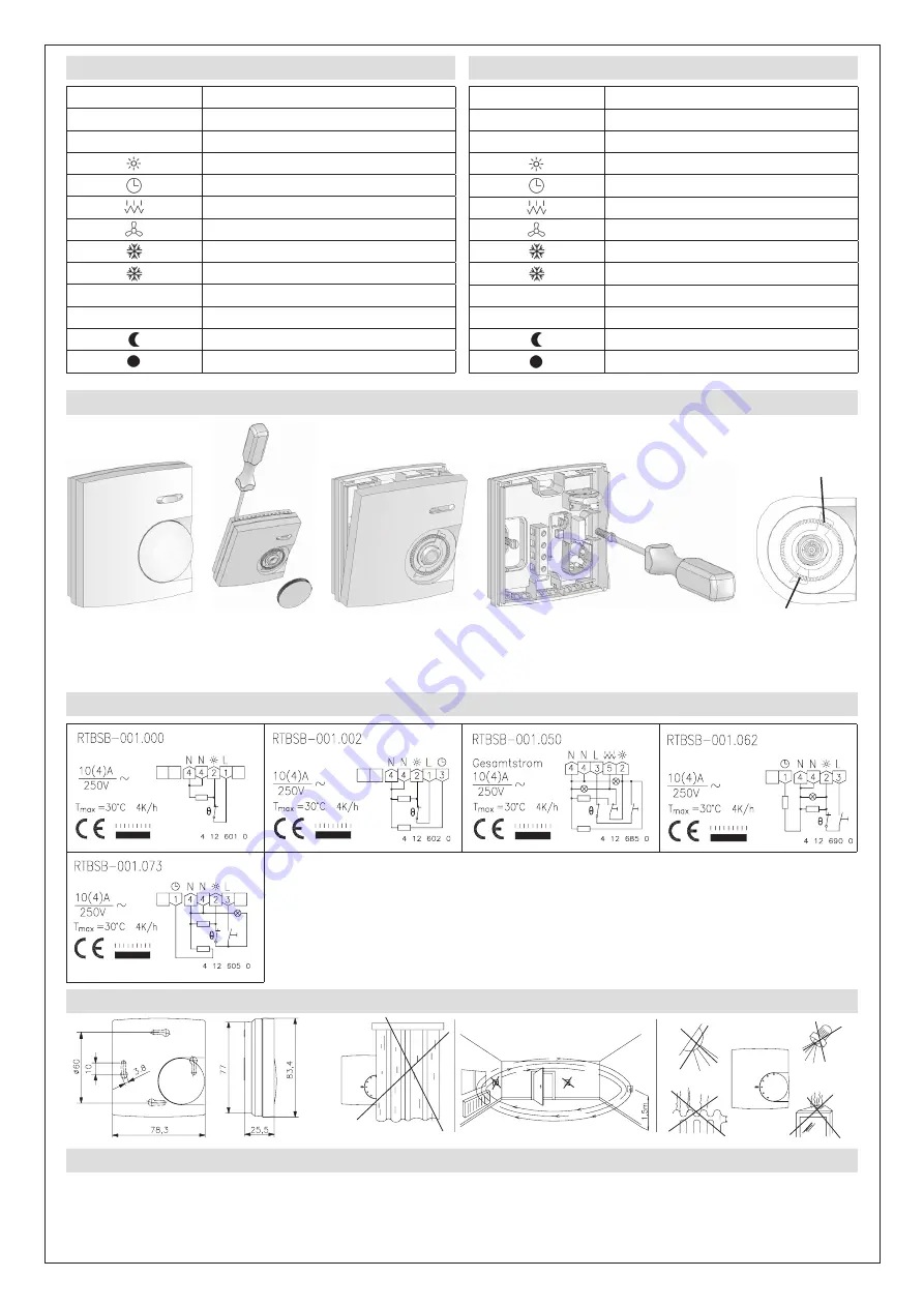
7. Anschluss-Schaltbilder / Connection diagram
8. Montagehinweis und Maßbild / Mounting information and dimensional
9. Gewährleistung / Warranty
Die angegebenen technischen Daten wurden durch uns jeweils in einem dafür geeigneten Prüf- und Testumfeld (hierzu geben wir auf Anfrage Auskunft) ermittelt und stellen
nur auf dieser Grundlage die vereinbarte Beschaffenheit dar. Die Prüfung der Eignung für den vom Auftraggeber / Kunden vorgesehenen Verwendungszweck oder den Einsatz
unter den konkreten Gebrauchsbedingungen obliegt dem Auftraggeber / Kunden; hierfür übernehmen wir keine Gewährleistung. Änderungen vorbehalten.
We determined the technical data provided in an inspection and test environment suited to this task (we are happy to provide details on request) and this data only presents the
agreed properties on this basis. The purchaser / customer is responsible for checking the suitability of the use or usage intended by the purchaser / customer under the specific
conditions of use; we do not accept any liability for this. We reserve the right to amendments.
6. Installationshinweise / Installation information
Einstellfahne für mini-
malenTemperaturwert
Pin for the setting of
the minimum tempera-
ture value
Einstellfahne für maxi-
malen Temperaturwert
Pin for the setting of
the maximum tempe-
rature value
5. Klemmen- und Bediensymbole
Symbol
Bedeutung
L
Phase Versorgungsspannung
N
Neutralleiter
Ausgang Heizen
Temperatur-Absenkeingang (ECO-Eingang)
Zusatzheizung
Ventilatorausgang
Als Klemmensymbol: Ausgang Kühlen
Als Bediensymbol: Frostschutz ca. 5°C
I
Ein
O
Aus
Temperatur-Absenkbetrieb (ECO-Betrieb)
Temperatur-Wohlfühlpunkt
5. Terminals and operating symbols
Symbol
Explanation
L
Supply voltage phase
N
Neutral conductor
Heating output
Temperature decrease input (ECO input)
Additional heating
Fan output
Terminal symbol: Cooling output
Operating symbol: Frost protection (approx 5°C)
I
ON
O
OFF
Temperature decrease mode (ECO mode)
Thermal well-being point


