background image

GEM80

7. Hilscher System software (SyCon)

Issue 002 (07/05)

Fieldbus Technical Manual T2035

Page 22

MUST HAVE

1.


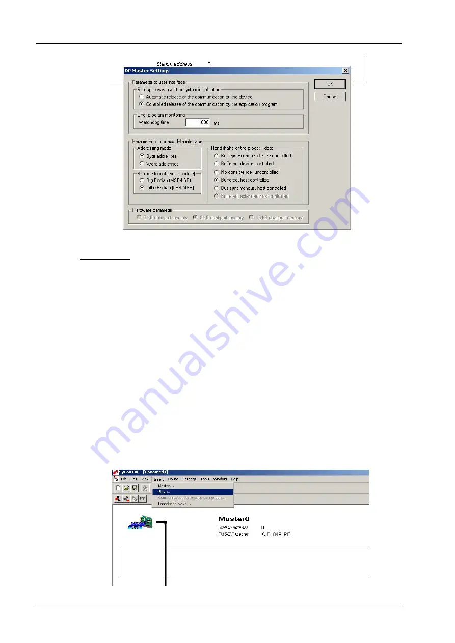
Controlled release of the communication by application program

2.


Byte addresses

3.


Little Endian

4.


Buffered, host controlled

The Watchdog Time can be adjusted to suit your application (default 1000ms). It
should not be set to a value  lower than twice the longest GEM80-500 Ladder scan
rate.

Once configured 

OK

 to return to network overview.

7.4.2


Inserting Slaves

To do so select - 

INSERT

 then 

SLAVE

Use the mouse to position slave on the line representing the network cable, right click
to drop.

Summary of Contents for GEM80

Page 1: ...GEM80 Fieldbus Modules Technical Manual Publication No T2035EN Issue 002 07 05 ABCD...

Page 2: ...to Pn 9 and Pn 23 to Pn 25 10 5 2 6 Version Buffer Pn 10 to Pn 12 and Pn 26 to Pn 28 10 5 2 7 Reserved Parameters 10 5 3 System Configuration 11 6 Maintenance and Fault Finding 12 6 1 Fixed F Table 1...

Page 3: ...ported protocols are Profibus FMS DP CANopen and DeviceNET Master functionality is supported in each case The Fieldbus plug in modules are peripherals of the GEMLAN T compatible processor module Up to...

Page 4: ...mon Technical Specification 2 1 Electrical Power Consumption 650mA from host GEM80 5v LED Indication Green LED Run Yellow LED Ready Communication Red LED Error 2 2 Physical Dimensions 90 x 96 x 23 L x...

Page 5: ...re Layout Issue 002 07 05 Fieldbus Technical Manual T2035 Page 4 3 Hardware Layout Fieldbus Front panel and Module Profibus shown Power Converter Fieldbus front panel Module Identification Rotary Swit...

Page 6: ...ins and watchdog connector Move the controller to a suitable location and proceed as follows noting that all references to left and right refer to the controller when viewed from the front a Release t...

Page 7: ...truction a WARNING Insertion or removal of modules with the equipment energised will cause malfunction of the equipment 4 3 Module Identification A rotary switch located on the fieldbus module PCB ach...

Page 8: ...re Note If the parameters are subsequently altered they will be recognised and validated by the GEMLAN T Module following a recompilation During the validation Fieldbus communication is halted If the...

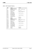
Page 9: ...ut table quantity Pn 10 Version table letter In LS byte MS byte 0 Pn 11 Version table offset Pn 12 Version table quantity Pn 13 Reserved Must be 0 Pn 14 Reserved Must be 0 Pn 15 Reserved Must be 0 MOD...

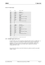
Page 10: ...3 0048 P324 2050 P325 100 P326 0046 P327 F525 P328 25 P329 0 P330 0 P331 0 G Table G1100 Length 50 entries 100 bytes H table H2050 Length 100 entries 200 bytes F Table F525 Length 25 entries 50 bytes...

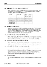
Page 11: ...ffer Pn 4 to Pn 6 and Pn 20 to Pn 22 These 3 entries table letter offset and quantity together define a buffer for the receipt of plant data The table must exist have write access and have sufficient...

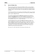
Page 12: ...by communicating directly with the Fieldbus module This method is suitable for monitoring the network operation but should not be used for system configuration downloading As it communicates directly...

Page 13: ...F379 F393 F380 F394 F381 F395 F382 F396 F383 F397 F384 F398 F385 F399 Presence Indication See section 6 1 4 6 1 1 Error Code The Error Code field and the associated pointers are used to identify prob...

Page 14: ...nd power cycle the GEM80 or replace the faulty Fieldbus module The following rungs of ladder program will cause a user requested F1 trip if any configured module should fail An F1 trip will also be pr...

Page 15: ...of the active devices detected on the communications link It is recommended that the application monitors this bit array and takes appropriate action on loss of I O Word 0 bit 0 represents the master...

Page 16: ...0320 01 05 2003 4 7910 6 Device Type BCD 9040 10794090 8 0000 10 Serial Number BCD 2200 00000022 12 Memory size BYTE 08 8Kbytes 13 Type BYTE 03 Type 3 14 Model ASCII 31 Model 1 15 43 16 49 17 Identifi...

Page 17: ...tion to the Hilscher System software The Hilscher System software is supplied unlicensed and as such can only be used to generate a configuration with one slave It can be used however to download mult...

Page 18: ...proceed with NEXT Select Components to load window You require the CIF Device Driver and your selected Fieldbus All other options can be de selected to save disk space if required For this example we...

Page 19: ...ieldbus Technical Manual T2035 Page 18 7 4 Hilscher Profibus System software SyCon Operation Guide To run the utility select SyCon from program files This will launch the SyCon EXE Main Window Network...

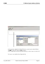
Page 20: ...eldbus system 7 4 1 Start to build a representation of your Fieldbus system Start by inserting the Fieldbus master module This represents the module installed in GEM80 500 To do so select INSERT then...

Page 21: ...T2035 Page 20 For this example highlight the CIF104P PB as the required master module Profibus Use ADD to select the master and OK to confirm A list of module types and associated board reference num...

Page 22: ...edit the master parameters for operation with the GEM80 Double click the master to launch the Master Configuration window shown below Note you can change the master station address from the default o...

Page 23: ...Endian 4 Buffered host controlled The Watchdog Time can be adjusted to suit your application default 1000ms It should not be set to a value lower than twice the longest GEM80 500 Ladder scan rate Once...

Page 24: ...ind a suitable slave you need to import the configuration file supplied with the slave device Importing these files is covered at the end of this document The slave is now added to the configuration f...

Page 25: ...Manual T2035 Page 24 Slaves will have different modes of operation the explanation of which will be covered in the specific slave module documentation To select the correct mode of operation for your...

Page 26: ...Publication T2011EN GEM80 Ethernet Modules Technical Manual for configuration and commissioning instructions The Sycon configuration tool automatically connects to the well known port number 1099 the...

Page 27: ...are scans the hardware at the specified IP Address and lists all compatible Hilscher hardware found You must select the target device for the configuration download tick the box Pofibus is identified...

Page 28: ...ad the configuration If you proceed the progress of the download will be shown and if no problems are encountered the progress window will clear automatically on completion 7 5 1 Common Error Message...

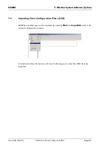
Page 29: ...Manual T2035 Page 28 7 6 Importing Slave Configuration Files GSD GSD Files and Bitmaps can be imported by selecting FILE then Copy GSD whilst in the network configuration window A standard window fil...

Page 30: ...Spares Service and Support For spares and support for this product please contact ALSTOM POWER CONVERSION WEST AVENUE KIDSGROVE STAFFORDSHIRE ST7 1TW ENGLAND UK Tel 44 0 1782 781000 Email psc_kidsgro...

Reviews: