background image

38

Measurement Modes

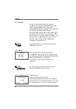
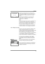
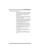
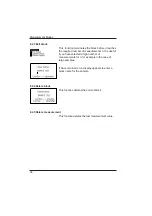
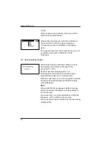
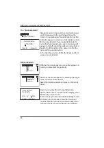
The measuring interval can be changed before a
sequence is started. Therefore press the mode
wheel to open the Continuous submenu.

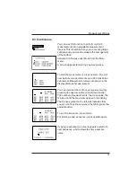
The longest measurement interval possible is 9
seconds, the shortest 0 seconds for continous
measuring. The interval slightly increases when
thickness sensor is activated.

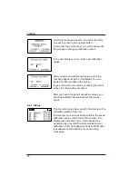
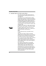
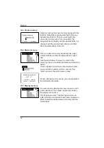
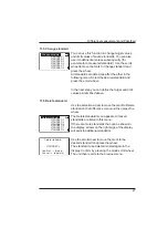
8.4 Basic mode

The selection options are limited to the most
essential in Basic mode. This also greatly simplifies
operation in this mode.

You can select geometry and thickness sensor and
perform calibration. In addition, all functions in the
Setup menu item are available.
Basic mode is useful if you want to interrupt a
series of measurements and quickly perform some
other measurements in the middle without leaving
the series of measurements.

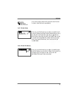
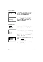
Once these other measurements are complete, you
can use

to return to the point where you interrupted the
series of measurements.

Continuous

Main menu

Measuring interval

*

Summary of Contents for 4440

Page 1: ...Additives Instruments A member of Measure what you see micro gloss Manual...

Page 2: ...ardner GmbH Lausitzer Str 8 D 82538 Geretsried Germany Tel 0 800 gardner 0 800 4273637 49 8171 3493 0 Fax 49 8171 3493 140 BYK Gardner USA 9104 Guilford Road Columbia MD 21046 USA Phone 800 343 7721 3...

Page 3: ...erefore in addition to our products we offer many VALUE ADDED services Technical Sales Force Technical Application Support Application and Technical Seminars Repair Certification Service BYK Gardner i...

Page 4: ...3 Change names numbers 21 5 4 Overview of main menu 22 6 Calibrate 23 6 1 Autodiagnosis 23 6 2 Calibrate 24 6 2 1 Gloss 24 6 2 2 Thickness 24 6 2 3 Change cal values 25 6 2 4 State 26 6 2 5 Scale glo...

Page 5: ...3 Sensor setting combi 40 10 Memory 41 10 1 Memory 41 10 2 Select memory 41 10 3 Create memory 42 10 4 Delete memory 42 10 5 Display memory 42 11 Difference measurement and Pass Fail 44 11 1 Differen...

Page 6: ...3 Interface 50 13 1 Installation 51 14 Standards 52 15 Technical Data 54 16 Errors and Warning Messages 56 17 Cleaning and Maintenance 58 18 Service and Certification 59 19 Copyright 61 Table of conte...

Page 7: ...6...

Page 8: ...uipped with safety features Nevertheless read the safety warnings carefully and use the product only as described in these instructions to avoid accidental injury or damage No claims of product liabil...

Page 9: ...danger of injury caused by electricity This sign points out additional information DANGER The term DANGER warns of possible severe injuries and danger to life WARNING The term WARNING warns of injuri...

Page 10: ...nder adverse conditions after harsh treatment during shipping Safety advices for batteries Do not crush or dismantle do not heat or incinerate do not immerse in any liquid This may cause explosion or...

Page 11: ...continuous humidity and condensation Avoid splashing with water chemicals or other liquids Please use only accessories that are available for the unit Only devices that meet the requirements for low v...

Page 12: ...n case you intend not to use the instrument for a longer period of time take out the battery Additonal information on use You will find the technical data for all system components on the respective m...

Page 13: ...lectometers that direct light onto the surface at different angles geometry can be used Measurement units are equipped with standard geometries of 20 60 or 85 All three of these geometries are integra...

Page 14: ...with Measurement device Protective holder with integrated calibration tile Traceable certificate Software easy link and USB driver on CD USB cable Bluetooth adapter with driver on CD Operating manual...

Page 15: ...t equipment for micro gloss 20 4422 for micro gloss 60 4462 for micro gloss 85 4487 for micro TRI gloss 4434 and micro TRI gloss micro gloss 60 S 4464 micro TRI gloss S 4438 mirror type highly reflect...

Page 16: ...the measuring unit for operation service The device runs on oneAA 1 5 V alkaline or 1 2 V NiMH rechargeable battery Use only alkaline batteries or NiMH rechargeables AA LR6 Depending on the exact bran...

Page 17: ...ttery with the positive top end first into the battery compartment and set the battery compartment cover in place again Lock the cover by turning it one eighth of a rotation to the right 3 3 External...

Page 18: ...guidance and displaying measurement values 3 Signal lamp green measurement active red error green flashing Bluetooth connection active 4 Operate button used to activate measurements 5 Protective holde...

Page 19: ...using the measuring unit please store it in the protective holder In this way the measurement optics are protected from dirt and dust and the calibration standard is always readily available The oper...

Page 20: ...broken down into the following elements A When Difference measurement is turned on the name of the standard that is selected is displayed here B If Memory is selected the memory area that is selected...

Page 21: ...angle to the right of a function indicates that selecting this function will take you to a sub menu A check mark on the right indicates that the function in question has been activated You can use the...

Page 22: ...haracter turn the scroll wheel When you press the wheel the arrow jumps to the next character After you have adjusted the last character or number confirm your input by pressing the wheel When you ent...

Page 23: ...Select standard if saved Enter up to 50 standards and limits for Pass Fail Delete individual standards Enter change limit values for Pass Fail The following can be used together simultaneously Mode Sa...

Page 24: ...ws for a long term calibration so that a new calibration is required only about once a week Beyond that calibration is only necessary if there are significant weather changes see under 6 2 It is recom...

Page 25: ...to adjust before calibrating and using the unit Use the path shown on the left side to reach the Calibrate menu option 6 2 1 Gloss To begin calibration press the scroll wheel The calibration process...

Page 26: ...strate instead of on the supplied metal plate 6 2 3 Change cal values The gloss values of the calibration standard in the holder included with delivery are saved in the measuring device During automat...

Page 27: ...you confirm the new value by pressing the scroll wheel the value will be accepted After you have changed all necessary values you should recalibrate the measurement device as usual 6 2 4 Status This m...

Page 28: ...ee the Section on Practical measuring suggestions Move the mark to the desired entry and press mode A check mark identifies the Scale that is selected After you switch the Scale the unit must not be r...

Page 29: ...6 4 Checking standard We recommend the regular use of a separate test standard for control of test equipment The frequency of this verification depends on the conditions of usage for example monthly...

Page 30: ...e set in the standards at 20 60 and 85 7 1 Paints and varnishes plastics and similar materials The various geometries are distinguished according to their fields of application as follows Semi gloss s...

Page 31: ...ress it as a reflectance You can select this in the Scale menu Notes Proper measurements are only possible on level surfaces Measurements on dirty scratched or otherwise distorted areas of the test sp...

Page 32: ...ment of the substrate It is therefore advisable to perform the zero calibration on the uncoated metal which is used for the object to be measured Surface roughness also influences the measure ment of...

Page 33: ...performed without statistical evaluation in Sample mode The results can be saved and compared with a standard refer to Memory or Difference When Memory is turned on a name is suggested after every me...

Page 34: ...mpared with a standard These functions must be previously activated refer to Memory or Difference Measurement Modes When Memory is turned on a name is suggested after all measurements of a sample bloc...

Page 35: ...Infi is written to the memory When the instrument is switched off the last setting remains active 8 2 1Number of measurements You can adjust the number of measurements per sample or per block with thi...

Page 36: ...ement value of the sample Range The difference between the maximum and minimum value Std Dev The standard deviation of the sample Difference The difference between the sample and a target value Pass F...

Page 37: ...ts n It is useful if you have selected a high number of measurements for n for example in the case of large samples If Save is turned on a display appears to enter a block name for the sample 8 2 4Del...

Page 38: ...easurements up to 99 times at the set interval Measurement values are shown in the display after each measurement You can interrupt the continuous measurement by pressing the operate button hold it do...

Page 39: ...ited to the most essential in Basic mode This also greatly simplifies operation in this mode You can select geometry and thickness sensor and perform calibration In addition all functions in the Setup...

Page 40: ...ently set angle combination is indicated in the Geometry menu by a check mark Select the desired combination with the scroll wheel and then confirm by pressing mode When Save is turned on switching th...

Page 41: ...ess setting to Combi the measurement will be run through in the sequence Fe NFe As the measurement takes place on a ferromagnetic substrate the procedure will be finished directly after the Fe measure...

Page 42: ...A check mark indicates if the function has been activated Turning on Memory automatically selects the area in memory that is predefined for the currently set geometry for example M20 60 When you press...

Page 43: ...the scroll wheel to move the mark to the memory area you would like to delete and press the wheel A menu appears in which you can decide whether you would like to delete just the content of the memory...

Page 44: ...e sample name is displayed in the highlighted field Turning the wheel switches the display to the next sample with its corresponding values Which values are displayed in the columns for example mean v...

Page 45: ...s automatically selected If no standard is available choose the function Measure standard or Create standard to continue 11 2 Measure standard We recommend to perform several readings on the standard...

Page 46: ...another one 11 3 Select standard To select an existing standard use the arrow to move the mark to Select standard and then press the wheel The first standard appears in the display The target value m...

Page 47: ...ne standard With the three angle device a menu first appears in which you can select the geometry After that the menu appears for selecting the target value minimum and maximum Select the desired vari...

Page 48: ...tion wheel to move the mark to Delete standard in the Difference menu and then press the wheel The Delete standard menu appears All saved standards are listed in this menu If there are more standards...

Page 49: ...time of the measurement available for data transfer to a PC The date and time are not lost even when the battery is changed If you would like to change the time setting use the scroll wheel to move th...

Page 50: ...select the display language Use the scroll wheel to move the mark to the desired language and press the wheel 12 6 Info You can use this menu option to find the following information Catalog No Seria...

Page 51: ...easy link program is included with delivery for this purpose The transferred data are displayed immediately in a test report For data transfer you can use the USB cable included with delivery or the w...

Page 52: ...y the system and the hardware assistant opens 1 Choose Install from a list and click the button Next Then select the folder USB Driver from the easy link CD The driver setup begins Note that if a wind...

Page 53: ...chen Reflectometer as a means for gloss assessment of plane surfaces of paint coatings and plastics BS 3900 D5 Methods of test for paints Measurement of specular gloss of non metallic paint films at...

Page 54: ...uctive basis materials Measurement of coating thickness Amplitude sensitive eddy current method ASTM B 499 Measurement of Coating Thicknesses by the Magnetic Method Nonmagnetic Coatings on Magnetic Ba...

Page 55: ...link included Power supply 1 MignonAlkaline AA LR6 or rechargeable NiMH Battery 1 5VDC max 0 1A Rechargeable 1 2VDC max 0 1A External power supply USB 5VDC max 0 1A Dimensions WxLxH 48 x 155 x 73 mm...

Page 56: ...rate Fe magnetic e g iron NFe non magnetic e g aluminium Sonde One point Measurement range 0 500 m 0 20 mil Accuracy 1 5 m 2 of measured value Min substrate thickness Fe 0 20 mm 8 mil NFe 0 05 mm 2 mi...

Page 57: ...s again However if a change in climate cannot be considered as the cause of the problem you should check whether the standard is clean Please call Service Autodiagnosis has determined an impermissible...

Page 58: ...or all measurements Yes It may help to test the calibration with an additional standard if one is available Calibration correct Is the test surface completely even and does the measuring device have g...

Page 59: ...damaged standards Since the surfaces of the standards are highly sensitive cleaning must be undertaken with great care To clean standards use a new lint free cloth dust free lens paper or an optical...

Page 60: ...for maintenance and recertification We clean the optics check all functions test and if required adjust the measured values by using reference standards You will receive a certificate which includes t...

Page 61: ...SA BYK Gardner USA 9104 Guilford Road Columbia MD 21046 USA Phone 1 301 483 6500 Fax 1 301 483 6555 China BYK Gardner Shanghai Office Room 1407 SIPAI PLAZA 103 Cao Bao Road Shanghai 200233 P R China P...

Page 62: ...esult of adapting the device to new information and improvements Copyright 2008 BYK Gardner GmbH All rights reserved No portion of the software documentation or other accompanying materials may be tra...

Page 63: ...260 020 398 E 0812...

Reviews: