background image

9

4.  Getting started

You can start a measurement

• 

with temp gard as data logger 


- according to the standard settings for the  


measurement parameters 


- change of the measurement parameters  


in the setup menu measurement parame- 


ters  

• 

by loading an Organizer

The measurement with the temp-gard as a data 

logger is described in the following.

The measurement with an organizer loaded is 

described in the temp-chart manual.

4.1  Starting the temp-gard logger

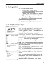
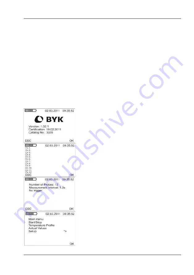
When the temp-gard logger is switched on, the 

status of the setup settings will be displayed:

Screen 1: Firmware version, Certification and Cat. 


     No.

Screen 2: Ch xx: Probe name, press OK 

Screen 3: No. of Probes – Measurement interval –  


     Trigger

Screen 4: Menu Connect the thermocouple probes  


      to the temp-gard instrument.

Start the measurement by pressing the start/stop 

key.

Note:

 Make sure that the thermal barrier and the 

heat sinks have cooled down completely after the 

previous measurement.

Make sure that the heat sinks are inserted in both 

halfs of the thermal barrier.

Place the temp-gard in the lower part of the ther-

mal barrier.

Make sure that all gaskets are clean and without 

defects.
Place the temperature probe cables side by side 

on the gasket of the thermal barrier and lock the 

box with the upper part.
Attach the thermocouple probes to the object.

Getting started

Summary of Contents for BYK Temp-gard 12p

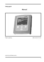
Page 1: ...Additives Instruments A member of Measure what you see temp gard 6p temp gard 12p Manual...

Page 2: ...1 temp gard Manual Patent pending 255 021 547 E 1103 www byk com instruments...

Page 3: ...ion Therefore in addition to our products we offer many VALUE ADDED services Technical Sales Force Technical Application Support Application and Technical Seminars Repair Certification Service BYK Gar...

Page 4: ...1 4 6 Special Notes on the Thermal Barrier 11 5 Main menu 14 5 1 Start Stop 14 5 2 Temperature profile 15 5 3 Actual values 15 5 4 Setup 15 6 Setup 16 6 1 Measurement Parameters 16 6 1 1 Number of Pro...

Page 5: ...4 Table of contents Service 22 10 Copyright 24...

Page 6: ...s play and USB mem ory stick con nec tion for easy data trans fer temp gard sys tem USB mem ory stick inter face pro vides easy data trans fer for in the field or in plant loca tions Long bat tery lif...

Page 7: ...l bar rier 1 Set of heat sinks 1 Probe for air tem per a ture mag net 3m PT 3131 1 Inter face cable to PC 2 AA Alka line bat teries Oper at ing man ual Cer tifi cate Car ry ing case Object tem per a t...

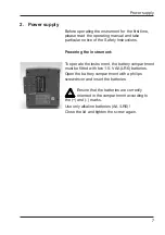
Page 8: ...trument To operate the instrument the battery compartment must be fitted with two 1 5 V AA LR6 batteries Open the battery compartment with a philips screwdriver and insert the batteries Ensure that th...

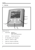
Page 9: ...ter Button Switch on Select function Start Stop a measurement 2 esc Button takes you one level up 3 UP Down Button Navigation 4 USB Port 1 Transfer via cable 5 USB Port 2 Transfer via USB Stick 6 Temp...

Page 10: ...re version Certification and Cat No Screen 2 Ch xx Probe name press OK Screen 3 No of Probes Measurement interval Trigger Screen 4 Menu Connect the thermocouple probes to the temp gard instrument Star...

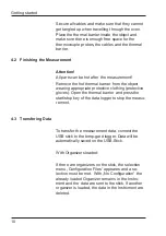
Page 11: ...lothing protective gloves Open the thermal barrier and press the start stop key of the data logger to stop the measu rement 4 3 Transfering Data To transfer the measurement data connect the USB stick...

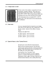
Page 12: ...own This serves a better mixture of the different compo nents Maximum duration time at 100 C 212 F up to 8 5 hours at 200 C 392 F up to 2 5 hours at 250 C 482 F up to 2 0 hours 4 6 Special Notes on th...

Page 13: ...tem perature lower than 10 C If the cooling agent has remained solid it is sufficient to cool down the heat sinks for 8 hours at a temperature lower than 20 C Make sure that mechanically damaged heat...

Page 14: ...13 temp gard Data Loggers Store in a dust free environment Remove batteries when storing for more than two to three weeks Return to BYK Gardner annually for calibration Getting started...

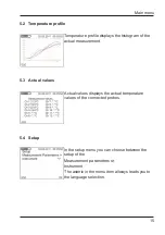
Page 15: ...perature data of the connected probes Setup Definition of measurement and instrument parameters 5 1 Start Stop To start the measurement place the cursor on the Start Stop position of the display and p...

Page 16: ...rement 5 3 Actual values Actual values displays the actual temperature values of the connected probes 5 4 Setup In the setup menu you can choose between the setup of the Measurement parameters or Inst...

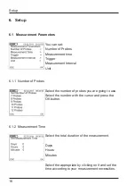
Page 17: ...nit 6 1 1 Number of Probes Select the number of probes you are going to use Select the number with the cursor and press the OK button 6 1 2 Measurement Time Select the total duration of the measuremen...

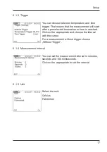
Page 18: ...rature or time is reached Click on the appropriate and choose the interval with the cursor For a measurement without trigger choose Without Trigger 6 1 4 Measurement Interval You can set the measureme...

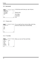
Page 19: ...In the instrument menu you can choose Display time Time Date Language Info 6 2 1 Display time You can set the time interval after which the instrument shuts down automatically 6 2 2 Time Date Here yo...

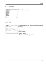
Page 20: ...19 Setup 6 2 3 Language Choose the Language 6 2 4 Info This menu displays the following information about the device Version Serial number Module version Maximum internal temperature...

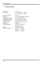
Page 21: ...0 readings per channel Sampling interval 0 1 sec up to 24 hrs Temperature Range 0 400 C 32 752 F Battery Capacity 0 5 sec interval 50 hrs Display Color 79 x 60 mm 3 1 x 2 4 in Interface USB 2 0 Therma...

Page 22: ...out whether the cooling agent has changed form solid to liquid state If the cooling agent is still in a solid state the heat sinks need to cool down for 8 hours at a temperature lower than 10 C If th...

Page 23: ...you send us your instrument for maintenance and recertification We clean the optics check all functions test and if required adjust the measured values by using reference standards You will receive a...

Page 24: ...rsorgungseinheit X X X X X X berpr fung der Taktzeiten X X berpr fung der Temperaturwerte X X X X X berpr fung der Z hleinrichtung berpr fung des Druckkopfes X berpr fung des lstandes X X X X Vermessu...

Page 25: ...d as a result of adapting the de vice to new information and improvements Copyright 2011 BYK Gardner GmbH All rights reserved No portion of the software documentation or other accompanying materi als...

Page 26: ...255 021 547 E 1103...

Reviews: