


19
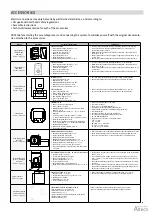
ACCESSORIES
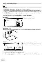
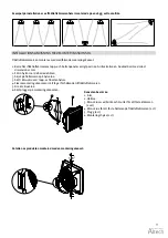
Electric connections may only be made by well-trained electricians, and according to:
• Occupational health and safety regulations
• Assembly instructions
• Technical documentation for each of the accessories
NOTE! Before starting the assembly process and connecting the system, familiarize yourself with the original documenta-
tion attached to the accessories.
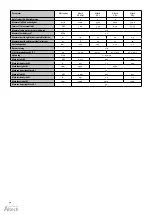
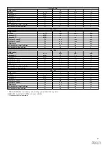
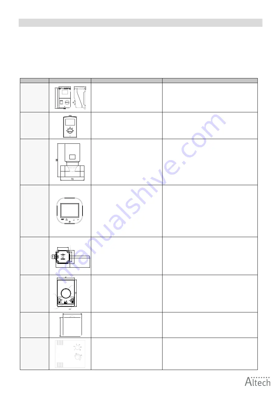
Model
Illustration
Technical specifications
Comments
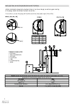
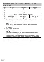
Speed regulator
(VR Mini, VR1,
VR2, VR3)
Part no: 6704779
90
91
164
145
SPEED REGULATOR
• Power supply voltage: 230 V AC +/- 10%
• Allowable current output: 3 A
• Control mode: step control
• Number of control levels: 5
• Type of protection: IP54
• Assembly methods: on a wall
• Work environment parameters 0…35°C
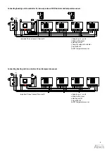
• Do not connect more than one VR 1/VR 2/VR 3 device to one rotation
controller and more than four VR Mini devices due to the values of
permissible output currents.
• Minimal distance between particular fans installed – both vertical and
horizontal – 20 cm.
• We recommend the execution of power supply connection with a min. 3 x
1.5 mm
2
wire
• Accessory drawings present the visualizations of model products only.
Speed regulator
(VR Mini)
Part no: 6704781
SPEED REGULATOR
• Power supply voltage: 230 V AC +/- 10%
• Allowable current output: 0.6 A
• Control mode: manual
• Number of control levels: 3
• Type of protection: IP54
• Work environment parameters 0…35°C
• Do not connect more than one VR Mini device to one controller
• Minimal distance between particular fans installed – both vertical and
horizontal – 20 cm.
• We recommend the execution of power supply connection with a min. 3 x
1.5 mm
2
wire.
• Accessory drawings present the visualizations of model products only.
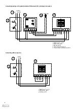
Two-way valve with
VR Actuator
Part no: 6704775
TWO-WAY VALVE
• Connection diameter: 3/4”
• Operation mode: on/off
• Maximum differential pressure 90 kPa
• Airflow degree factor kvs: 4.5 m
3
/h
• Work environment parameters: 0–60°C
VALVE ACTUATOR
• Power consumption: 1 W
• Power supply voltage: 230 V AC +/- 10%
• Closing/opening time 3/3 min
• Item without supply: closed
• Type of protection: IP54
• Work environment parameters: 0–60°
• Two-way valve should be installed on the return (outlet) pipeline.
• Accessory drawings are only a visualisation of sample products.
• Power connection should be done with a cable min. 2 x 0.75 mm
2
.
• Accessory drawings are only a visualisation of sample products.
Controller EC
Part no: 6704784
CONTROLLER EC
• Device operation: touch buttons
• Power supply: 230 V AC
• Maximum output current for valve or valves with
actuator: 3(1) A
• Temperature measurement: -10 ... +99 °C ; NTC10K
• Outputs:
- 1 analog output 0-10V (8 bit, Imax = 20 mA)
- 2 relays outputs (250 VAC, AC1 500 VA dla 230 VAC)
• Communication: Modbus RTU
• Parameters of working environment: temperature:
0–60 °C, humidity: 10 - 90%, without condensation
• Display: blue backlight
• Dimensions: 86 mm x 86 mm x 17 mm
• Protection level: IP20
• Used for control all types of EC units
• Touch control panel
• The main on / off switch (ON / OFF)
• Stepless adjustable fan speed of the EC motor
• Built-in thermostat with possibility weekly programing
• Continuous mode
• Function of heating, cooling and ventilation
• Possibility of using external temperature sensor
• RS 485 with ModbusRTU
• Suggested cross sections of electrical cables:
- L, N: 2 x 1 mm
- H, C: 2 x 1 mm
- AO, GND: 2 x 0,5 mm LIYCY
- TS; TS: 2 x 0,5 mm LIYCY
- RS 485: 2 x 0,75 mm LIYCY
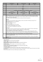
Room temperature
sensor EC
Part no: 6704785
39
37
51
49
59
2x
φ
4.5
ROOM TEMPERATURE SENSOR EC
• Resistant sensing element: NTC 10K
• Ingress protection rating: IP66
• Mounting method: wall mounted
• Maximum length of the signal cable: 100 m
• Parameters of the working conditions: -20...+70 °C
• Temperature measurement range: -20...+70 °C
• Dimensions: 36 x 49 x 71 mm (w/o a probe)
• Suggested diameter of supply cable (shielded cable):
2 x 0.5 mm
2
• NTC temperature sensor should be installed in the representative location
• Avoid places directly exposed to sunlight, electromagnetic waves etc.
• The accessory drawings are only a visualisation of sample products
Wall-mounted air
curtain / VR heater
controller
Part no: 6704773
10
25
15
20
30
1
2
3
4
WALL-MOUNTED AIR CURTAIN / VR HEATER CONTROLLER
• Supply voltage: ~230/1/50
• Permissible initial current: 6(3 A)
• Range of regulation: 10–30 °C
• Accuracy of regulation: +/- 1 °C
• Level of protection: IP30
• Assembly method: on plastered walls
• Parameters of working environment: from -10 to +50 °C
• The maximum length of the conductor, from the curtain to the programming
device, is 100 m.
• It is recommended to make a connection using a conductor of the min.
size 5 x 1 mm
2
or 6 x 1 mm
2
depend on the option of connection (see the
schemes)
• The drawings with the accessories contain only visualisations of sample
products.
• The controller does not constitute an integral part of the curtain. It is an
optional device, which may be replaced with any programming device or
switch that conforms to the 60335 standard.
Speed regulator
Part no: 6704782
74
74
SPEED REGULATOR EC (0–10 V)
• Supply voltage: ~230/1/50
• Permissible initial current: 0,02 A for 0–10 V
• Working mode: manual
• Output signal: 0–10 V DC
• Level of protection: IP30
• Power connection should be done with a cable min. 3 x 0.75 mm
2
.
• Accessory drawings are only a visualisation of sample products.
Potentiometer with
thermostat VR EC
Part n0: 6704783
POTENTIOMETER WITH THERMOSTAT VR EC
• Power suply: ~230/1/50 V/ph/Hz
• Permissible load: 0,02 A for 0–10 V
• Setting range: 5…40 °C
• Temperature measurement integrated in the device
• Output signal 0–10 V DC
• Protection rating: IP30
• Power connection should be done with a cable min. 2 x 0.75 mm
2
.
• Accessory drawings are only a visualisation of sample products.
Summary of Contents for VR Mini
Page 1: ...Heating unit Fl ktluftv rmare VR Mini VR1 VR2 VR3 1 12 Check us on EN Manual SV Manual...
Page 24: ...24 Notes...
Page 46: ...46 Anteckningar...
Page 47: ...47 Anteckningar...


