20
START-UP INSTRUCTION
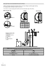
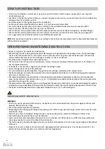
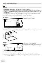
• Prior to any installation or maintenance work, disconnect the device from the power supply and secure it against
accidental power-up.
• Use filters in the heating system. Before you connect the pipes to the device, you should clean/rinse the installation by
draining a few litres of water out of it.
• Install vent valves at the highest point of the installation.
• Install cut-off valves directly behind the device, so it can be easily disassembled.
• Secure the device against pressure increase according to the permitted maximum pressure value of 1.6 MPa.
• Pipe connections need to be free from any stresses and loads.
• Prior to the first start-up of the heater, check the pipe connections (vent and collector air-tightness, installed fittings).
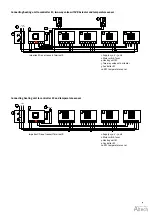
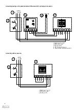
• Prior to the first start-up of the heater, check the electric connections (connection of accessories, power supply, fan).
• It is suggested to use additional external current differential protection.
NOTE!
All connections should be carried out, according to this technical documentation and the documentation delivered
with automation equipment.
OPERATION AND MAINTENANCE INSTRUCTION
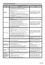
• Device casing does not require any maintenance.
• Heat exchanger needs to be regularly cleaned of dirt and grease. Especially before the heating season, the heat exchanger
needs to be cleaned with the use of compressed air on the side of the air guides (but the device does not need to be
disassembled). Pay attention to the exchanger’s lamellas, as these are delicate.
• If lamellas bend, straighten them with a special tool.
• The fan motor does not require any maintenance. It may only require cleaning of the protective mesh, fan blades and
dust and grease deposits.
• If the device is not used for a long time, disconnect the voltage supply.
• Heat exchanger does not have fire protection.
• It is recommended to periodically blow through the heat exchanger, preferably with compressed air.
• The heat exchanger can freeze (fracture) when the room temperature falls below 0 °C and the heating agent temperature
decreases at the same time.
• The level of air pollutants should meet the criteria allowable concentrations of pollutants in indoor air, for non-industrial
areas, the level of dust concentration up to 0.3 g / m
3
. It is forbidden to use device for the duration of the construction works
except for the start-up of the system.
• The equipment must be operated in rooms used throughout the year, and in which there is no condensation (large fluctuations
in temperature, especially below the dew point of the moisture content). The device should not be exposed to direct UV rays.
• The device should be operated at the supply water temperature up to 130 °C with working fan.
2
3
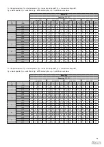
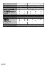
Motor kW
3 x 400 V
1,5 mm
2
2,5 mm
2
4,0 mm
2
6,0 mm
2
0,55
246 m
–
–
–
0,75
200 m
333 m
–
–
1,10
146 m
244 m
390 m
–
1,50
109 m
180 m
290 m
435 m
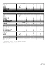
Motor kW
3 x 400 V
Amp
0,55
1,7
0,75
2,2
1,10
3,0
1,50
4,0
Kopplingsschema för djupbrunnspumpar
unDerhÅll
Djupbrunnspumpen är i sig själv underhållsfri. ett
normalt slitage vid pumpning av rent vatten märks
först efter mycket lång tid i drift, dvs pumpen förlorar
kapacitet. Dock skall anläggningens elektriska del un-
derkastas en fortlöpande kontroll av tex nätspänning.
strömförbrukning, manöverorganens elektriska och
mekaniska funktion. fukt, oxidation, brända kontakter
etc. Det är också lämpligt att fortlöpande kontrol-
lera pumpmotorns lindningsvärden. avvikelser från
föreskrivna lindningsvärden tyder på driftstörningar.
pumpar som ej är i drift under längre perioder kan utan
problem förbli installerade.
en kortare drift c:a 5–10 minuter per månad förhindrar
att pumpens roterande system fastnar pga. avlagringar.
ej installerade pumpar skall lagras i sval lokal och verti-
kalt. före återinstallation, kontrollera motorns fyllning
respektive att det roterande systemet ej fastnat. en rätt
installerad undervattenspump har alla förutsättningar
att ge en lång och säker drift förutsatt att den erhåller:
• rätt nätspänning
• rent kallt vatten
• rätt startfrekvens
Det är viktigt för pumpen och anläggningens funktion,
att regelbundet eller minst en gång per år kontrollera
luftmängden i hydroforen. observera att antalet starter
per timma ej får överskrida 20 st. Den situationen
kan uppstå om hydroforen som används har felaktig
luftmängd. Är anläggningen monterad med membran-
hydrofor skall lufttrycket vara 0,2 bar under pumpens
starttryck. om tex. starttrycket är 1,5 bar så skall luft-
trycket vara 1,3 bar. innan pump-anläggningen startas,
kontrollera dessa värden. vid kontroll av membranhy-
droforens lufttryck skall den alltid vara tom på vatten.
luftventilen på tanktoppen är av samma typ som finns
på bildäck. tryckmätning, påfyllning samt avtappning
av luft sker på samma sätt som på ett vanligt bildäck.
Djupbrunnspump: Maximal kabellängd i
meter avstånd pumpmotor – mätarcentral
Kabeldimensionering enligt tabellerna är vår generella
rekommendation för att garantera djupbrunnspumpens
goda funktion under normala förhållanden. avvikande
driftsförhållanden som spänningsfall på elnätet, drift
via elverk, varvtalsreglering med frekvensomriktare m
m kan medföra annan dimensionering lokala stark-
strömsföreskrifter skall beaktas.
reKoMMenDeraD
unDervattensKabel
h07rn-f
Djupbrunnspump.
effekt och märkström
säkerhetsinstruktion
installation och drift av roterande maskiner och ap-
parater kan vid icke fackmässig och oriktig hantering
ge upphov till omfattande person- och materialskador.
bidra till en säker arbetsmiljö samt en ökad livslängd
hos den levererade materielen genom att observera
följande varningssymboler.
elektrisk anslutning får enbart göras av
behörig elektriker i enlighet med stark-
strömsföreskrifterna.
pumpa
aldrig
andra vätskor än de pumpar-
na är avsedda för. Detta gäller i synnerhet
eldfarliga, explosiva eller frätande vätskor.
överskrid aldrig maximalvärdena för tryck
och temperatur. trycksatta rörsystem skall
alltid förses med godkänd säkerhetsventil.
vid arbete på pumpen (apparaten) skall
alltid arbetsskyddsbrytaren vara frånsla-
gen.
läs
alltid
den medlevererade montage-
föreskriften. om den har förkommit eller
förstörts, kontakta oss.
tryckkärl monterade i pumpanläggningar
och rörsystem skall vara typgodkända av
ackrediterat kontrollorgan i enlighet med
arbetsmiljölagen 3 kapitlet , 8 paragra-
fen. typgodkännandenumret skall vara
angivet på tryckkärlet och leverantören är
på anmodan skyldig att överlämna giltigt
typgodkännandecertifikat.
FARA
FARA
VARNING
VARNING
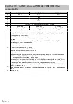
INDUSTRIAL SAFETY INSTRUCTION
WARNING!
• Prior to any work connected with the device, the device must be disconnected from the power supply and be secured
properly. Wait until the fan stops.
• Use stable assembly platforms and hoists.
• Depending on the heating agent temperature, piping, parts of the casing, heat exchanger surface can be very hot, even
after the fan stops.
• There may be some sharp edges! During transport, use protective gloves, protective clothing and safety shoes.
• The health and safety instructions must be followed.
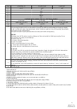
• Loads can be fastened only in places designed for it in a transport unit. While devices are lifted by an assembly unit,
their edges need to be secured. Distribute the load evenly.
• The device needs to be protected against moisture and dirt and should be stored in rooms secured against atmospheric
influences.
• Disposal: Take care to dispose of used materials, packaging material and spare parts in a safe way, one which is not
harmful to the environment and is in accordance with local regulations.
Summary of Contents for VR Mini
Page 1: ...Heating unit Fl ktluftv rmare VR Mini VR1 VR2 VR3 1 12 Check us on EN Manual SV Manual...
Page 24: ...24 Notes...
Page 46: ...46 Anteckningar...
Page 47: ...47 Anteckningar...


