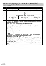
background image

21

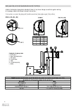
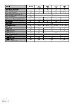
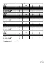
Altech VR Mini, VR1, VR2, VR3
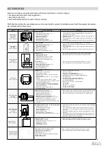
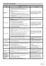
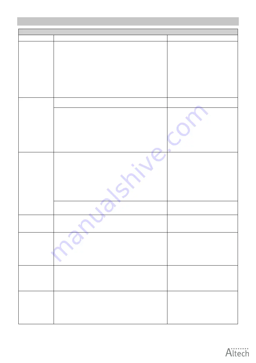
Problem

Checkpoints

Description

Heat exchanger 
leaking

• Assembly of the exchanger connections with two wrenches (adjustment), 

which safeguards against internal twisting of the collectors.

• Check if the leakage may be associated with mechanical damage to the

exchanger.

• Vent valve or drain plug leaking.
• Heating agent parameters (pressure and temperature) – should not exceed

permitted values.

• Type of heating agent (it cannot be aggressive to Al and Cu).
• Circumstances when the leakage appears (e.g. during the first, tentative

installation start-up, when the installation is filled up after the heating agent
has been drained) and outside temperature at the time of failure (risk that the
exchanger may freeze).

• Possibility of operating in aggressive conditions (e.g. high concentration of

ammonia in the air in a sewage-treatment plant).

Pay special attention that the exchanger may 
freeze during winter time. 99 % of registered 
leakages appear during installation start-up/
pressure tests. The defect can be removed by 
pulling back vent or drain valve.

Fan works too loud

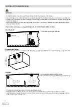
• Assembly of the device is in conformity with this manual (e.g. distance from 

wall/ceiling).

Min. 40 cm

• Device appropriately leveled.
• Correctness of electric connections and qualifications of the wireman.
• Inlet current parameters (e.g. voltage, frequency).
• Use of rotation controller different from Altech regulators. 
• Noise at lower gears (possible controller failure).
• Noise only at higher gears (regular situation explained by aerodynamic

characteristics of the device, if there outlet air chokes).

• Type of other devices operating in the building (e.g. induced draught fans) –

intensified noise caused by simultaneous operation of many machines.

• Does the fan rub against the casing.
• Is the fan evenly screwed to the casing.

Level of operating noise of devices is perceived
subjectively. If the device is made of plastic, it 
should operate quietly.It is recommended to 
unscrew the clamping screws and tightening 
them up again. If the fault does not disappear, 
contact Altech Technical Support.
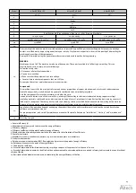
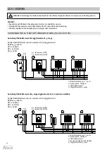
Fan does not work

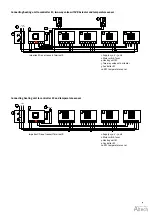
• Correctness and quality of electric connections and qualifications of the

wireman.

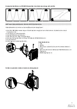
• Is there an additional bridge between required engine terminals (diagram in 

the manual) – U1 – TK (TB).

• Inlet current parameters (e.g. voltage, frequency) on the clamp block of fan

engine.

• Correctness of operation of other devices installed in the building.
• Correctness of wire connections on the engine side acc. to the manual, in

comparison to wires clamped in the engine terminal strip.

• PE conductor voltage (if present, may mean there is a break-down).
• Is N conductor correctly connected to the fan or regulator, or is the connection 

of U2 clamps on the motor and regulator made correctly.

Electrical connection need to be done strictly 
according to the electric diagrams in the manual. 
If there is no bridge between U1 and TK(TB) 
clamps, the motor lacks thermal protection and 
may break – burn.

• Damage or installation of controller different from regulator.

It is recommended to check the device/ speed 
controller by connecting the heater directly to 
power supply.

Damaged casing

• Circumstances when it was damaged – notes on the bill of ladings, stock issue

confirmation, condition of the box.

If the casing is damaged, make photos of the 
box and device, confirming that the device serial 
number on the device and on the box are the 
same.

Regulator –  rotation 
controller does not 
work/ it is burned

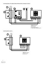
• Correctness – quality of electric connections (wires accurately positioned

in electric clamps, cross-section and the material wires are made of) and
qualifications of the wireman.

• Only 1 controller connected to 1 device.
• Inlet current parameters (e.g. voltage, frequency).
• Correctness of operation after connecting “in short” (skipping regulator, i.e.  
   connections L and TB, N and U2, PE and PE) to the power network.
• Check that the knob wasn't damaged during installation or use.

For the controller, the following must also be 
checked:
•circuit breaker
•correctness of connection to the controller
•use of shielded conductors
•control conductors, which should be located 
away from the working conductors

Actuator does not open
the valve

• Correctness of electric connections and qualifications of the wireman.
• Correctness of the thermostat operation (characteristic tick sound during 

changeover).

• Inlet current parameters (e.g. voltage).

The most important is to check whether the 
actuator responded to the electric impulse within 
11 s. If the motor is damaged, you need to switch 
actuator operation to manual (MAN), which 
mechanically opens the valve. If the motor is 
damaged, change actuator.

Programmable 
thermostat does not 
send any signals to 
the actuator/ controls
the operation of the
heating system 
wrongly

• Correctness of electric connections and qualifications of the wireman.
• Correctness of the thermostat operation (characteristic tick sound during 

switchover).

• Connecting a few motor of devices directly to the thermostat

(permitted only if contactor is used).

• Inlet current parameters (e.g. voltage).
• When was the last time the sensor was calibrated. 
• The thermostat is incorrectly connected directly to the motor.

RDE thermostat is powered by batteries, that 
need to be replaced (every 2 years). Also, the 
sensor needs to be periodically calibrated. 
Warranty is not valid if the thermostat was 
directly connected to the motor. If the sensor 
incorrectly measures the temperature, it should 
be calibrated (instructions in the catalogue).

TROUBLE SHOOTING

Summary of Contents for VR Mini

Page 1: ...Heating unit Fl ktluftv rmare VR Mini VR1 VR2 VR3 1 12 Check us on EN Manual SV Manual...

Page 2: ...2 2017 132 Manual english 3 Manual svenska 25 Distribueras av Distributed by Dahl Sverige AB Teknisk Support Technical support Telefon 020 55 11 00 E post tks altech nu...

Page 3: ...12 Instruction for venting heat carriers 13 Adjusting the air guides 13 Connection to the power supply 13 ELECTRIC DIAGRAMS 14 Electric diagrams for AC heating units VR Mini VR1 VR2 and VR3 14 Electri...

Page 4: ...ens funktion ng per r kontrollera rvera att antalet starter t Den situationen anv nds har felaktig nterad med membran 2 bar under pumpens r 1 5 bar s skall luft anl ggningen startas ntroll av membranh...

Page 5: ...FLOW FAN maximum working temperature is 60 C and nominal power supply voltage is 230 V 50 Hz AC Engine protection is IP54 and insulation class F for EC motors IP is 54 Air feed is performed by the ax...

Page 6: ...0 37 2 7 2 8 25 1 0 12 0 4 1100 10 6 48 6 0 47 4 8 6 43 4 0 38 2 8 6 6 38 0 29 1 8 1 9 25 2 0 08 0 2 Tz inlet water temperature Tp outlet water temperature Tp1 inlet air temperature Tp2 outlet air te...

Page 7: ...6 4 3 7 25 8 0 31 0 7 2400 24 5 50 4 1 09 6 3 20 44 8 0 88 4 4 15 5 39 2 0 68 2 8 5 3 26 6 0 23 0 4 Tz inlet water temperature Tp outlet water temperature Tp1 inlet air temperature Tp2 outlet air temp...

Page 8: ...1 6 Maximum horizontal air stream range m 14 23 22 25 Maximum vertical air stream range m 8 12 11 12 Water capacity dm3 1 12 1 25 2 16 3 1 Ferrule diameter 3 4 Weight of the device AC EC kg 13 14 21 2...

Page 9: ...e m 12 9 7 Altech VR2 Fan speed III II I Air flow m3 h 4850 3600 2400 Noise level AC dB A 56 51 40 Noise level EC dB A 54 49 38 AC motor electric power W 280 220 190 EC motor electric power W 250 190...

Page 10: ...is necessary to maintain a minimum distance of 0 4 m from the wall or the ceiling otherwise the device can malfunction the fan can be damaged or its operating noise can increase If the device will be...

Page 11: ...th minimum dimension of 12 mm 2 Insert sleeves into the holes 3 Slide holder arms onto the sleeves 4 Insert M10 screws into the top and bottom sleeves 5 Fix the assembly bracket position in relation t...

Page 12: ...EATER 2 POWER OPERATED VALVE 3 VENT VALVE 4 CUT OFF VALVE 5 FILTER 6 CIRCULATION PUMP 7 BOILER SUPPLY RETURN Note Maximum operating pressure of the medium for water coils is 16 bar tested pressure 21...

Page 13: ...ectric wires NOTICE We recommend connecting the wires to the terminal block with pre installed bushings Altech VR Mini VR1 VR2 VR3 5 x 1 5 mm2 Altech VR MINI VR1 VR2 VR3 Power supply 3 x 1 5 mm2 Contr...

Page 14: ...2 units VR3 1 unit Connecting heating unit to 3 level wall controller and two way valve with VR Actuator Maximum number of heating units connected to one controller VR Mini 4 units VR1 2 units VR2 2...

Page 15: ...regulator AC Maximum number of heating units connected to one controller VR Mini 4 units VR1 VR2 and VR3 1 unit 1 Supply 230 V 50 Hz 2 Main switch fuses 4 Heating unit AC 11 Thermostat AC 1 Supply 230...

Page 16: ...erminal X VOLCANO HMI EC HY NO CONNECT GND A B 1 2 3 4 5 6 7 8 4 PE L N 10V Ain Black White Green Yellow Red Brown Blue Green Yellow 10V Ain Important Do not connect Terminal X GND A B PE L N 1 2 3 4...

Page 17: ...way valve with actuator 9 Controller EC 10 NTC temperature sensor 1 Supply 230 V 50 Hz 2 Main switch fuses 4 Heating unit EC 9 Controller EC 10 NTC temperature sensor Important Do not connect Termina...

Page 18: ...en Yellow Connecting heating unit to potentiometer with thermostat EC and temperature sensor Connecting with accessories 1 Supply 230 V 50 Hz 2 Main switch fuses 4 Heating unit EC 1 Supply 230 V 50 Hz...

Page 19: ...ng environment temperature 0 60 C humidity 10 90 without condensation Display blue backlight Dimensions 86 mm x 86 mm x 17 mm Protection level IP20 Used for control all types of EC units Touch control...

Page 20: ...och br nda kontakter pande kontrol avvikelser fr n driftst rningar e perioder kan utan r m nad f rhindrar nar pga avlagringar i sval lokal och verti era motorns fyllning met ej fastnat en r tt alla f...

Page 21: ...onnected to the fan or regulator or is the connection of U2 clamps on the motor and regulator made correctly Electrical connection need to be done strictly according to the electric diagrams in the ma...

Page 22: ...nnection 3 Make sure that the equipment is at zero voltage 4 Cover or isolate nearby components that are still live To energize the system apply the measures in reverse order Components The machines c...

Page 23: ...indings the winding insulation is incinerated during copper recycling insulating materials cables and wires electronic waste capacitor ect plastic parts impeller junction box winding cover ect rubber...

Page 24: ...24 Notes...

Page 25: ...lutning av v rmesystem 34 Anvisning f r avluftning av fl ktluftv rmare 35 Justering av luftledarna 35 Ansluta till str mf rs rjning 35 ELSCHEMAN 36 Elscheman f r AC fl ktluftv rmare VR Mini VR1 VR2 oc...

Page 26: ...med AC och EC motorer Altech VR Mini 3 20 kW 2 100 m3 h Altech VR1 5 30 kW 5 300 m3 h Altech VR2 8 50 kW 4 850 m3 h Altech VR3 13 75 kW 5 700 m3 h ANV NDNING tillverkningshallar lager fabriksbutiker i...

Page 27: ...memediet kan ha en glykolhalt p upp till 50 2 FL KT MED AXIELLT FL DE maximal arbetstemperatur r 60 C och nominell kraftf rs rjningssp nning r 230V 50 Hz AC motorernas kapslingsklass r IP54 isolerings...

Page 28: ...0 37 2 7 2 8 25 1 0 12 0 4 1100 10 6 48 6 0 47 4 8 6 43 4 0 38 2 8 6 6 38 0 29 1 8 1 9 25 2 0 08 0 2 Tz tilloppstemperatur Tp returtemperatur Tp1 temperatur inloppsluft Tp2 temperatur utloppsluft Pg...

Page 29: ...86 4 3 7 25 8 0 31 0 7 2400 24 5 50 4 1 09 6 3 20 44 8 0 88 4 4 15 5 39 2 0 68 2 8 5 3 26 6 0 23 0 4 Tz tilloppstemperatur Tp returtemperatur Tp1 temperatur inloppsluft Tp2 temperatur utloppsluft Pg v...

Page 30: ...f r horisontell luftstr m m 14 23 22 25 Maximal kastl ngd f r vertikal luftstr m m 8 12 11 12 Vattenkapacitet dm3 1 12 1 25 2 16 3 1 R ranslutning 3 4 Vikt f r produktens AC EC kg 13 14 21 21 21 5 21...

Page 31: ...tr m m 12 9 7 Altech VR2 Fl kthastighet III II I Luftfl de m3 h 4850 3600 2400 Bullerniv AC dB A 56 51 40 Bullerniv EC dB A 54 49 38 Effekt hos AC motor W 280 220 190 Effekt hos EC motor W 250 190 162...

Page 32: ...ter tappas ur Ett minsta avst nd p 0 4 meter fr n v ggen eller taket kr vs I annat fall kan funktionsfel uppst fl kten kan skadas eller kat buller vid drift Om produkten installeras p en v gg eller h...

Page 33: ...12 mm 2 F r in hylsorna i de borrade h len 3 Skjut p h llarmarna p hylsorna 3 S tt i M10 skruvar i topp och bottenhylsor 4 Fixera monteringskonsolen i r tt l ge i f rh llande till fl ktluftv rmaren 5...

Page 34: ...LIC SYSTEM 1 UNIT HEATER 2 POWER OPERATED VALVE 3 VENT VALVE 4 CUT OFF VALVE 5 FILTER 6 CIRCULATION PUMP 7 BOILER SUPPLY RETURN Obs Maximalt drifttryck f r fl ktluftv rmaren r 16 bar testat tryck 21 b...

Page 35: ...ingarna ansluts till kopplingsplintar med f rinstallerade bussningar Altech VR Mini VR1 VR2 VR3 5 x 1 5 mm2 Altech VR MINI VR1 VR2 VR3 Huvudsp nning 3 x 1 5 mm2 Kontroll 0 10 V DC LiYCY 2 x 0 75 mm2 s...

Page 36: ...termostat AC och ventil med st lldon Antalet fl ktluftv rmare som kan anslutas till en v ggtermostat VR Mini 4 enheter VR1 2 enheter VR2 2 enheter VR3 1 enhet 3 runnspumpar d vara tom p vatten samma t...

Page 37: ...ntalet fl ktluftv rmare som kan anslutas till en v ggtermostat VR Mini AC 4 enheter VR1 VR2 och VR3 1 enhet 1 Str mf rs rjning 230 V 50 Hz 2 Huvudbrytare s kringar 4 Fl ktluftv rmare AC 11 V ggtermost...

Page 38: ...l X VOLCANO HMI EC HY NO CONNECT GND A B 1 2 3 4 5 6 7 8 4 PE L N 10V Ain Black White Green Yellow Red Brown Blue Green Yellow 10V Ain Obs Anslut inte kopplingsplint X GND A B PE L N 1 2 3 4 5 6 7 8 G...

Page 39: ...SNR N L N L 5 5 10 Obs Anslut inte kopplingsplint X 8 Pod czenie Volcano VR Mini VR1 VR2 VR3 VR D z silnikiem EC z regulatorem obrotw 0 10V Vout GND 230_N 230_L Q1 F1 0 1 L N PE 230V 1 2 11 7 2 Pod cz...

Page 40: ...ingar 4 Fl ktluftv rmare EC 10 NTC temperatursensor 12 Styrenhet med termostat EC GND A B 1 2 3 4 5 6 7 8 Q1 F1 0 1 L N PE 230V 1 2 4 12 PE L N L N NTC Ao GND NTC 5 10 15 20 25 30 1 3 2 3 10V Ain Blac...

Page 41: ...milj temperatur 0 60 C luftfuktighet 10 90 utan kondensation Display bl bakgrund M tt 86 mm x 86 mm x 17 mm Skyddsniv IP20 Anv nds f r styrning av alla EC enheter Touchkontrollpanel Huvudbrytare f r p...

Page 42: ...n driftst rningar e perioder kan utan r m nad f rhindrar nar pga avlagringar i sval lokal och verti era motorns fyllning met ej fastnat en r tt alla f ruts ttningar att att den erh ller gningens funkt...

Page 43: ...ll fl kten eller regulatorn eller r anslutningen av U2 kl mmor p motor och regulatorn korrekt gjord Elanslutningar m ste g ras exakt enligt elscheman i manualen Om det inte finns n gon bygel mellan U1...

Page 44: ...ingen r p nollsp nning 4 T ck eller isolera n rliggande komponenter som fortfarande r str mf rande F r att aktivera systemet genomf r stegen i omv nd ordning Komponenter Maskinerna best r till st rsta...

Page 45: ...leringen f rbr nns vid material tervinning av koppar isoleringsmaterial kablar och ledningar elektronikavfall kondensator osv plastdelar fl kthjul kopplingsdosa lindningsk pa osv gummidelar neopren De...

Page 46: ...46 Anteckningar...

Page 47: ...47 Anteckningar...

Page 48: ...Altech betyder noggrant utvalda produkter med h g kvalitet till bra pris Distribueras av Dahl Sverige AB Teknisk Support Telefon 020 58 30 00 E post tks dahl se www dahl se 201 199...

Reviews: