Instruction manual 91/104 V9.2
Commissioning
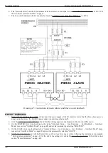
6. It is now possible to insert the F1 fuse tern, or connect the power supply to the coil of the K1 contactor to provide the three-
phase power to the L1-L2-L3 inputs of the two drives. In case of use of a DC-BUS power supply, from this point it is
possible to power it and make it supply the voltage on DC+ and DC-.
7. The “Autotune” function shall be used for the calculation of the motor parameters; It will be run simultaneously on both
motors which must therefore have been disconnected from the mechanics and must be both free to move.
8. Follow the paragraph ”Autotune for the calculation of optional parameters“ from page 58, but before enabling the Master
drive with the DEN command, you must also have activated the autotune function on the Slave drive.
9. Always following the above paragraph if everything has been done on a regular basis, you should see both motors rotating
and autotune as indicated. At the end of the procedure, the parameters must be saved on both drives.
10. To calibrate the performance of the motors and the response of the various adjustment loops it is convenient to do the tests on
the Master motor alone; when you have found the ideal parameters you can insert into the Slave drive using the keypad and
LCD display.
11. In order to run the Master motor alone, you need to disable the Slave motor with the ” Slave Running“ menu (see page 50) on
the Master drive display, setting it to “Disabled”.
NOTE:
If the motors have been mechanically disconnected you cannot enable the Slave motor otherwise it could go on speed
escape since it does not have a mechanical connection to the Master motor.
12. After deactivating the Slave motor, you can continue following the instructions of paragraph ”Motor speed adjustment“ from
page 59 in order to obtain the desired operation of the Master motor.
13. At this point you must disable the Master motor and copy the modified parameters also to the Slave drive using the LCD
display of the drive.
14. Rehabilitate the Slave motor
with the ”Slave Running“ menu (see page 50) of the Master drive by setting it to “Enabled”.
Save the parameters on the Master and Slave drives.
15. Switch off the switchboard and mechanically reconnect the motors to the machine transmission
16. Turn on the electrical panel and prepare all the equipment for operation. By enabling the Master motor, the Slave motor is
also enabled at the same time (the RUN LEDs of both drives must be switched on).
17. With a zero speed reference, the motors must stand still. If this is not the case, change the ”An.Inp.1 Offset“ parameter (see
page 39) of the Master drive.
18. Move to the parameter ”Contrast Torque“ (see page 50) to adjust the contrast torque of the two motors. Enable the system
and move the motors; change the above parameter until you get a smooth axis movement at all speeds and in both directions.
Generally, a value of 5 to 30 % is sufficient.
19. If the axis has not a smooth motion, you can use the “MASTER 2” mode, which uses a different algorithm.
At the end of all adjustments it is essential to save the parameters before turning off the services.
5.6.12 Spindle lock
5.6.12.1 Generality
This function is used to keep the motor shaft locked in space control, so the motor will always remain still even if the speed reference
has offset or even if the motor shaft is subjected to a torque of torsion.
The drive must be enabled (DEN=ON) and the digital input associated with the function (Spindle Lock) must be active.
5.6.12.2 Calibration
1. Set the digital input
to use for the "Spindle Lock" command from the "I/O Configure → Digital Inputs" menu and from the
destination selection menu on the desired input select the item "Spindle Lock" (see paragraph "Dig.Inp. X Dest“ on page 43).
If you want to change the logical state of command to activate the function, you must enter (or disconnect) the logical re -
versal setting of the input (see paragraph "Dig.Inp. X Sign“ on page 44). For safety it is better to check that there are no other
inputs for this function.
2. Set the digital signal output
“Reached Position" (if needed); the DO4 digital output is normally already set. To check, go to
the configuration menu "I/O Configure → Digital Outputs" and from the selection menu of the source of the desired output
go to check the item "Position Reach" (see paragraph "Dig.Op. X source“ on page 44). If you want to change the logical state
of the output when the motor is in position, you must insert (or disconnect) the logical reversal setting of the output (see
paragraph "Dig.Op. X Sign“ on page 45).
3. Use of the function
:
Suppose the motor is spinning at a certain speed.
The CNC slows the motor down to zero speed (Zero Speed output = true) reducing the speed reference.
At this point the CNC activates the digital input associated with “Spindle Lock " to keep the shaft locked.
The drive signals the output “Reached position " to indicate that the motor is in space control.
At this point the motor shaft does not even move by applying a torque of torsion.
Alter Elettronica s.r.l.
73


