Technical characteristics
Instruction manual 91/104 V9.2
[4] Only ultra-fast protective
fuses (for semiconductor protection) are essential for three
-phase or DC BUS inputs. Other
fuses do not provide a sufficient degree of protection and therefore, in case of failure, the drive can be severely damaged.
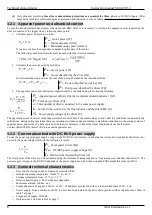
3.2.1 Apparent power and absorbed current
To size the transformer/self-transformer, inductance and EMC filter, it is necessary to calculate the apparent power required by the
drives connected to the supply line by following these points:
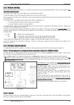
1. Calculate power from motor to load:
P
m
=
C
⋅
P
m=
motor power [W]
C = Torque dispensed [Nm]
Ω
= Maximum using speed [rad/sec]
If you do not know the usage data, consider the plate data of the motor.
The following conversion formulas must be used with other Units of measure:
C
[
Nm
]=
C
[
Kgm
]⋅
9,81
ω[
rad
/
sec
]=
n
[
giri
/
min
]
9,55
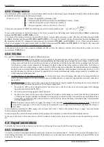
2. Calculate the power required by each drive:
P
c
=
P
m
⋅
1,5
P
m=
motor power [W]
P
c=
Power absorbed by the drive [VA]
and calculate the total power as the sum of the power absorbed by the individual drives:
P
t
=
P
c1
P
c2
P
c3
....
P
c=
Power absorbed by a drive [VA]
P
t=
Total power absorbed by drives [VA]
3. The apparent power and total current required shall be calculated using the following formulae:
P
a
=
P
t
⋅
1,73
d
2
P
a=
Apparent power delivered by the transformer/autotransformer [VA].
P
t=
Total power drives [VA].
d = Total number of drives connected to the same power supply.
I
u=
Current to be used to size the line inductor and the filter EMC [A].
V
a=
Power supply voltage of the drives [V].
I
u
=
P
a
1,73
⋅
V
a
The apparent power and current value thus calculated are valid only if the motors always work under the conditions considered in the
calculations. during normal operation there are variations in torque and speed leading to significant reductions in the average values of
apparent power and current. To have more exact values it is necessary to know the actual conditions of use of all motors.
Contact the ALTER Technical Office to examine special cases.
3.2.2 Current absorbed with DC-BUS power supply
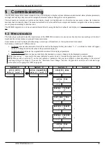
To size the power supply supply supply voltage to the DC-BUS it is necessary to calculate the total current required by the drives con-
nected to the power supply itself with the following formula:
I
t
=
P
t
V
dc
P
t=
Total power drives [VA]
V
dc=
DC-BUS power supply voltage [V]
I
t=
Total current required by drives [A]
The total power of the drives can be calculated using the formulas of paragraph above “Apparent power and absorbed current”. The
power supply voltage on the DC-BUS depends on the power supply used, but when using the PSR3 model this value is 650Vcc.
3.2.3 General technical characteristics
–
Execution for fixing on panel. Degree of protection IP20.
–
Ambient operating temperature: from 0 °C to +40 °C.
–
Storage temperature: from -10 °C to +70 °C
–
Relative humidity max.: 95 % without condensation.
–
Maximum altitude: 1000 m. a.s.l.
–
Single-phase service supply: 230Va.c. ±10 % – 500mA max (protection with external retarded fuses 250V – 1A).
–
Power supply: from a minimum of 60V to a maximum indicated on the drive plate. (protect with external fuses as show in
table 7 at page 7.
–
Frequency of supply: 50/60Hz.
–
Output current: As from table 2 at page 7.
8
Alter Elettronica s.r.l.


