Instruction manual 91/104 V9.2
Commissioning
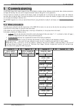
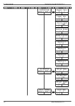
With reference to the above structure, the keys have the following functions to move between the menus:
•
Key “▲”: inside the same level, slide in vertical direction the various menus contained in the same group, upwards.
•
Key “▼”: inside the same level, slide in vertical direction the various menus contained in the same group, downwards.
•
Key “►”: button: go up to one level and display the 1st menu of the top level of that group.
•
Key “◄”: drops one level and returns to the previous menu of the lower level.
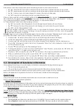
When you reach a menu that contains an editable parameter and after pressing the “►” key, you enter the “change parameter” mode
that is identified by the appearance of a “
“ character
in the bottom left corner of the display. If there is the character “=” in this posi-
tion, it means that the parameter displayed is read-only and therefore it is not possible to modify it.
In “Change Parameter” mode, the key function changes as follows:
•
Key “
▲”: increases the value of the parameter of a unit. Keeping it pressed increases the rate of increase.
•
Key “▼”: decreases the value of the parameter of a unit. Keeping it pressed increases the speed of decrease.
•
Key “◄”: exits the “change parameter” mode.
NOTE:
after changing a parameter it is essential to store it in the internal Flash memory, otherwise when the power supply
voltage of the auxiliary services is missing, the change is lost and the previous value returns. To do this, refer to the appropriate
paragraph”Memo Parameters“ on page 40.
Example:
suppose we want to change the maximum speed of the motor that is in the menu “Maximum Speed” which is part of the
group “Motor Parameters” which in turn is in the group “Quick Setup”, you have to do the following steps:
1. Press the button “◄” until you see any menu in Level 1 (see the lettering in the 2nd line of the display).
2. Look for the “Quick Setup” group by scrolling the various menus upwards by pressing the button.
3. Press the button “►” to switch to the 2nd level. You will see the group “Motor Parameters” which is what interests us.
4. Press the “►” button again to switch to the 3rd level. The parameter “Motor Type” will be displayed as it is the 1st menu of
the “Motor Parameters” group.
5. Press the“▼“button until you see the “Maximum Speed” menu.
6.
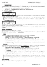
To change this parameter you need to switch to “Edit Parameter” mode. Therefore, you must press the “►” button once
again, which causes a “
“to appear in the bottom left corner.
7.
Press the key “▲” to increase the value or the ”▼“ key to decrease it. The change is used immediately by the drive.
8. When you read the desired value you have to press the key “◄” to exit the “Edit Parameter” mode.
9. At this point you can go back to level 1 by pressing the “◄” button 2 times, or switching to another parameter.
10. You can make all the necessary changes to the various parameters, but you have to remember to store the changes on the
Flash memory before removing the power of the services to the drive otherwise all changes are lost.
5.3 Description of functions in the menus
After supplying the auxiliary services on the display, an initial menu containing the following information appears:
1. The first line shows the product code.
2. The second line shows the version of Firmware loaded into the DSP (the software that runs the drive).
Both of these information must be communicated to our technical office, in case of request for advice or malfunctions.
Below is the explanation of the parameters that can be set from the menus, divided into the various groups.
Quick Setup
Group of menus that contain the minimum parameters that need to be set in order to make the drive work.
It also contains the most used calibration parameters.
Motor Parameters
Menu group to set the motor parameters. Without these data the drive cannot function properly and therefore all must be written fol -
lowing the indications of the plate on the motor. The parameters indicated in this group must be placed in the order as displayed as
some of them are linked to each other and one may limit the range of the other.
Selected gear
Indicates the currently selected speed range (Stage 0 or Stage 1). This menu is only visible if the “Electronic
Gear
Change " function
is active. With the switching of the speed range, some parameters (those indicated with * in the menu list from page 21) are switched.
For more information see the appropriate paragraph "Electronic gamma change“ from page 67.
Motor Type
Set the type of motor used:
•
Async. LowSpd
: asynchronous low speed motor (up to 11000 RPM). This type is usually set with normal asynchronous.
•
Async. HighSpd
: asynchronous high speed motor (up to 25000 RPM). This type is usually set with electro-spindles.
Alter Elettronica s.r.l.
35

