Instruction manual 91/104 V9.2
Commissioning
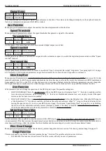
Maximum speed
Minimum
Maximum
Units of measure
100
11000 / 25000
RPM
Set the maximum speed that the motor must achieve when the speed reference is at most. The maximum limit depends on the mode
selected with the "Motor Type“ parameter (see page 35).
Normally this speed corresponds to the 10Vcc reference on analogue input 1 (AI1) if configuration or scaling has not been changed.
To check the value of the speed reference (analog or digital), you can check the parameter “Diagnostic → Speed Demand " (see page
45) while the drive is enabled and the motor runs regularly. On page 59 paragraph "Motor speed adjustment“ there is a complete
explanation of the precise calibration procedure of this parameter.
Maximum Voltage
Minimum
Maximum
Units of measure
Nominal Voltage
440
Volts (RMS)
Set the maximum motor voltage as read on the plate. If a maximum voltage above the rated voltage is not specified, it is advisable not
to change this parameter and leave it equal to the rated voltage.
Max. speed at Pn
Minimum Maximum
Units of measure
100
25000
RPM
Set the
maximum speed up to which the motor can reach at the Nominal Power
(plated data). This parameter must be written on
the motor plate or supplied by the manufacturer otherwise the motor may be damaged or not functioning properly.
In case this data is unknown, then it is advisable to leave the standard parameter that the drive calculates automatically. If during mo-
tor operation you see that the power delivered at high speed is not enough for machining, you can try to increase this value little at a
time until you find the right value. In any case it is advisable to contact our technical office.
NOTE:
Each time you change one of the following parameters: Nominal Voltage, Nominal Frequency, Motor Pole, Maximum
Voltage, the above parameter is automatically set to the value calculated by the drive.
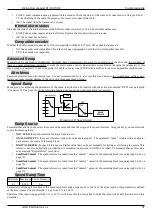
Feedback Type
Select the type of transducer mounted in the motor, choosing from the available ones:
•
TTL encoder
: always available (input on X4 connector).
•
Resolver
: selection possible only with optional 01/324 card (input on X14 connector).
•
Sin-Cos
: selection possible only with optional 01/325 card (input on X14 connector).
•
Phonic Wheel:
selection possible only with optional 01/326 card (input on X14 connector).
•
EnDat
: selection possible only with optional 01/327 card (input on X14 connector).
NOTE:
The selection of a certain transducer with this parameter involves the appearance or disappearance of some menus de-
pending on the utility or not with the selected transducer (see NOTE on page 21 "Menu structure”).
Encoder Lines
Minimum Maximum
Units of measure
Displayed only with
100
10000
PPR
Encoder, Sin-cos, phonic wheel.
Set the number of pulses per revolution (ppr) of the encoder mounted in the motor.
ABS signal C&D?
This parameter is only visible with SinCos transducer. It is used to indicate the type of SinCos encoder connected to the X14 con-
nector. The possible selections are as follows:
•
YES. The SinCos encoder has absolute channels, so there are the wires with the signal called C, C, D, D connected to the rel-
ative pins of the X14 connector (see section 5.5.2 on page 60).
•
NO. the SinCos encoder does not have absolute channels, but only incremental s zero signal.
Resolver Pole Pair
Minimum Maximum
Units of measure
Displayed only with
1
36
Number of pole pairs
Resolving
Set the number of polar pairs of the transducer resolver.
NOTE:
The “number of resolver poles" is generally indicated; since this parameter indicates the number of “pole pairs " it is ne-
cessary to divide the given data in half. EXAMPLE: Pole resolver n°4, the data “Resolver Pole Pair " = 2.
Alter Elettronica s.r.l.
37


