Instruction manual 91/104 V9.2
Commissioning
•
SumBlock Summ2
: The analogue output indicates the value of the sum 2 (Summ2) output of the summing block (see sec-
•
SumBlock Summ3
: The analogue output indicates the value of the sum 3 (Summ3) output of the summing block (see sec-
An.Out. X Value
Minimum Maximum Units of measure
-100.00
+100.00
%
Read-only parameter indicating the input signal of the analog output compensation block. See drawing 16 to see where this value is
read.
An.Out. X Gain
Minimum Maximum Units of measure
-2.00
+2.00
-
Set the multiplication factor of the “Value " signal in input to the calibration block. With this parameter you can amplify or reduce the
input signal to suit your needs. See drawing 16 to figure out where this parameter works in the calculation.
An.Out. X Offset
Minimum Maximum Units of measure
-10.00
+10.00
%
Set the value to add to the “Value " signal to create an outgoing offset. See drawing 16 to figure out where this parameter works in the
calculation.
An.Out. X Abs
With this parameter you can select whether to take the “Value " or its value without sign as input of the calibration block of the analog
output. The selections available are:
•
FALSE: The “Value " signal is used directly with the positive or negative sign.
•
TRUE: The “Value " signal is used as an absolute value (without sign), so always positive.
By activating this function it is possible to have an analog output always positive (or negative, just set the “Gain " with a negative
number), in case of use with unmarked display tools. See Drawing 16 to figure out where this parameter works in the calculation.
Digital inputs
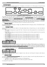
Menu group to configure and calibrate digital inputs. For simplicity it is advisable to see the following figure showing the internal cal -
ibration structure of a generic digital input.
The logical state of the terminal associated with the digital input is read and then you can then select whether to send the direct or lo -
gically reversed value out of the block.
Digital Input X
Menu group to configure the digital input X. Changes to the calibration values made in this group, act exclusively on the indicated di -
gital input and not on the others.
Dig.Inp. X Dest
Parameter that allows you to select the destination of the digital input. Using the keys you can select the destination among these:
•
NOT USED
: digital input is not used.
•
Rev.Speed Ref.
: the digital input (standard on DI1) controls the reversal of the motor direction.
•
Stage bit 0
: the digital input indicates the desired speed range. If the inversion of sign has not been activated, the meaning is
as follows:
━
0V: Selection STAGE 0 (Slow Range).
━
24V: Selection STAGE 1 (Quick Range).
•
Check STAGE 0
: the digital input controls the effective closing of the remote control of the connections of stage 0 (i.e. slow
range).
Alter Elettronica s.r.l.
43
Drawing 17: Digital input structure
Digital Input X
0/+24V → False/True
VALUE
REVERSE
NORM
SIGN
Destination selector


