Commissioning
Instruction manual 91/104 V9.2
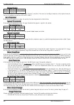
Digital Refer.
Minimum Maximum Units of measure
-100.00 % +100.00 %
-
With this parameter you can give a digital speed reference to the drive. This value can be changed manually via the keyboard or modi -
fied via a communication network (CAN BUS or other).
Aux Function
Menu group with parameters to adjust the auxiliary functions implemented within the drive.
Speed Threshold
Menu group with parameters to adjust the speed thresholds that generate a signal for the outside.
Threshold No. 1
Minimum Maximum Units of measure
0
9999
RPM
Set the speed of the motor beyond which the associated digital output is switched.
Speed reached
Minimum Maximum Units of measure
0.0 %
+10.0 %
-
Set the percentage difference between the set speed and the actual motor speed, to switch the digital output associated with the “Speed
reached” function.
Zero speed thr.
Minimum Maximum Units of measure
1
50
RPM
Set the speed threshold below which the motor is considered “stop " and signals the output “Stop motor " (see paragraph 5.6.1 on page
65). Normally with the standard parameter you get the best results, but in case of need it is possible to increase it.
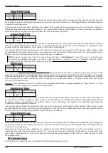
Drive Stop/Run
Menu group with parameters to set the “Stop/Run " function of the motor by controlling the digital input “DEN " (see page 19). Under
standard conditions, the DEN input enables and disables the drive but does not brake the motor; the reference and DEN control must
be managed by the CNC or the PLC to bring the motor up to zero speed. Instead, using the following parameters you can change the
DEN input function and make sure that, when this input is removed, the motor brakes until it stops and then disables the drive.
Den Function
With this menu you can change the operation of the DEN digital input. The possible settings are:
•
DRIVE DIS/ENAB: This is the standard mode. When the DEN input is at the logical level “1 " the drive is enabled and fol -
lows the set speed reference; when it is logically “0 " the drive is disabled and remains free, so it stops by inertia if the speed
reference has not been reset when enabled.
•
DRIVE STOP/RUN: This is a new mode that allows you to stop the motor before disabling the drive. When the DEN input is
at the logical level “1 " the drive is enabled and follows the set speed reference. When “0 " is logical, the drive brakes by fol-
lowing the speed ramp, if it is active (see REN input on page 19 and menu "Speed Ramp Time“ on page 40), or by blocking
the motor with the maximum available current (emergency brake) if the ramp is disabled. When the motor is stationary or
when the maximum time set in the next parameter is exceeded, the drive is disabled.
Motor Stop Time Max
Minimum Maximum Units of measure
0
65.5
Sec
Set the maximum time available to stop the motor with the DEN input, if the “Drive Stop/Run " operation has been selected (see pre-
vious parameter). This time starts as the speed ramp has reached Zero and serves as a safety in case for some reason the motor fails to
slow down until it stops. After the set time the drive disables and the motor stops by inertia (or with a mechanical brake).
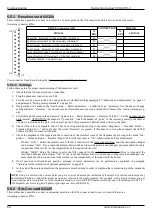
Elec. Gear Change
Menu group with parameters to adjust the electronic gamma change function
(see section "Electronic gamma change“on page 67).
Stage Function
This menu is used to enable the “electronic gamma change " function. The possible selections are as follows:
•
DISABLED: The function is deactivated. The drive works with only one set of parameters.
48
Alter Elettronica s.r.l.


