Instruction manual 91/104 V9.2
Commissioning
Position offset
Minimum Maximum Units of measure
-180
+180
degrees
This parameter allows to offset the position of the simulated encoder with respect to the true position of the motor.
Direction
With this parameter you can reverse the count direction of the simulated encoder. The possible selections are as follows:
•
NORMAL: positive direction
•
REVERSE: negative direction.
Torque filter
In this menu you can activate or disable a special filter inserted after the speed loop that allows to reduce vibrations due to speed
transducers not perfectly calibrated and undulating in resolver transducers.
Power supply from
Menu to select the source of the power supply (
only for model PWM3D-001
). The selections available are:
•
DC+ DC-: The voltage is given directly on the DC+ and DC- terminals by an external power supply which must precharge
the capacitors on the DC Bus and check the voltage so as not to exceed the maximum accepted by the drive (750Vcc) using a
clamp circuit or an in-line recovery system. The internal clamp circuit is NOT used.
•
L1-L2-L3: The voltage is given on the terminals L1, L2, L3 and the internal rectifier bridge is used. The drive performs the
precharge of capacitors on the DC Bus when it receives the input voltage. When the voltage on the DC Bus exceeds a certain
threshold, the Clamp circuit enters into operation that inserts the braking resistance.
•
L1-L2: (Only for drive size 1). The single-phase voltage is given on the L1, L2 terminals and the internal rectifier bridge is
used. The drive performs the precharge of capacitors on the DC Bus when it receives the input voltage. When the voltage on
the DC Bus exceeds a certain threshold, the Clamp circuit enters into operation that inserts the braking resistance.
5.4 Calibration and adjustments
Operations to be carried out:
1. Give 230Vac service power supply on the X10 connector.
2. Check that the LCD display lights up and that the letters indicating the drive model and firmware revision appear, otherwise
check the correct service voltage.
3. Check that no red LEDs are on.
Then make the adjustments indicated in the following paragraphs with reference to the paragraph "Menu structure“ from page 21 and
"Navigation in the menus“ from page 34 to enter the indicated data.
5.4.1 Setting motor parameters
In the case of use of the drive with an asynchronous motor, the necessary data to know are the following:
1. The motor nominal
voltage
.
2. The continuous service
current
that circulates in the motor when it is powered by the nominal voltage and delivers the
nominal torque.
3. The maximum current that can withstand the motor (serves only if you want to overload the motor during accelerations).
4. The nominal
frequency
at the voltage indicated in point 1.
5. The number of poles of the motor.
6. The maximum speed of the motor with the maximum reference. If the speed is greater than 11000 RPM, the mode must be
set to “Async. HighSpd. "
7. The maximum voltage that can be applied to the motor: this data must be higher than the nominal voltage. In case of doubt
you can set this value equal to the rated voltage.
8. The type of speed transducer mounted on the motor and its technical data.
Sometimes it may happen that not all these data are available on the license plate of the motor but that others are supplied with which
you can obtain the necessary parameters; some formulas for obtaining missing data are given in the paragraphs related to the descrip-
tion of the various motor setting menus ("Motor Parameters“ from page 35). In case of need you can contact the ALTER technical of-
fice for clarifications.
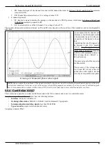
To clarify how the various parameters change motor operation, see Drawing 23:
Alter Elettronica s.r.l.
57


