Instruction manual 91/104 V9.2
Commissioning
5.5.5 Manual offset calibration
When the following transducer cards are used: 01/325, 01/326, 01/327, it is possible to calibrate the offset to compensate for incre -
mental sinusoidal analog signals.
This offset, if present, causes problems in the speed signal that is wavy and during operation makes the motor vibrate or makes the
adjustment unstable. To solve this problem, the drive automatically calculates the offset of the two incremental sinusoidal signals
(signals on X14 pins 3,4,6,7), after manual activation of the function.
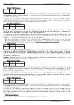
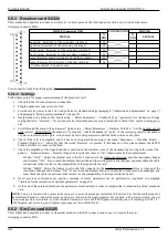
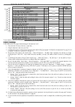
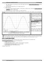
To manually start the offset calibration, you can follow these points:
1. The drive MUST be disabled (Led RUN off).
2. Move to the menu ”Diagnostic → Transduc. Board → Man Offset Calc”.
3.
Switch to “Edit Parameter” mode. So you have to press the "►" button once again, which shows a ”
“ in the bottom left
corner, press the key “▲” to enable the calibration cycle: the inscription becomes “ENABLED”.
4.
Spin the motor (at a speed above 50 RPM), then stop
turning the motor and let it
stop
for
inertia.
5. When the motor stops, the above menu will automatically become DISABLED.
6. At this point the calibration is over. You don't need to save the parameters.
5.6 Special functions
5.6.1 Zero speed motor signalling
5.6.1.1 Generality
This function is used to signal on a selectable digital output (usually matched to the DO1 output), when the motor is still. If the motor
speed is less than 2 RPM for a time greater than 500 mSec the signaling occurs and the associated output changes logical status and
leads to +24V or 0V if the inversion of sign is activated (see ”Dig.Op. X Sign“ on page 45).
5.6.1.2 Calibration
This function does not need calibration. To use it you have to go to the configuration menu "I/O Configure → Digital Outputs" and
from the selection menu of the source of the desired output go to select the item "Zero Speed" (see paragraph ” Dig.Op. X source“ on
page 44). If you want to change the logical state of the output when the motor is still, you must enable (or disable) the logical reversal
setting of the output (see paragraph ”Dig.Op. X Sign“ on page 45).
If the speed reference signal has an unstable offset, it may happen that the signaling does not occur; In this case you can change the
parameter "Zero speed thr.“ (see page 48) and increase it until you turn on the LED of the set digital output.
5.6.2 Motor brake control
5.6.2.1 Generality
This function is used to control the release of the parking brake of the motor using any digital output (usually combined with the DO2
output). If the drive is disabled and the motor is stationary (following the same conditions as in the previous paragraph) the signaling
occurs and the associated output changes logical status and leads to 0V or +24V if the inversion of sign is activated (see ”Dig.Op. X
Sign“ on page 45).
NOTE: This
output
is not used to control an “emergency brake”
but a “parking brake”. For this reason, the brake is controlled
only when the motor is stationary. A digital output associated with the "Drive Running" source may be used to activate an
emergency brake (see section ”Dig.Op. X source“ on page 44).
5.6.2.2 Calibration
This function does not need calibration. To use it you have to go to the configuration menu "I/O Configure → Digital Outputs" and
from the selection menu of the source of the desired output go to select the item "Motor Brake" (see paragraph ” Dig.Op. X source“ on
page 44). If you want to change the logical state of the brake control output, you must insert (or disconnect) the logical reversal setting
of the output (see paragraph ”Dig.Op. X Sign“ on page 45).
Normally when the motor brake is to be inserted, the output goes to 0V, so it removes power to the brake coil.
5.6.3 Motor temperature
5.6.3.1 Generality
This function is used to signal on a selectable digital output or to block the drive, when the motor has exceeded its maximum operat-
ing temperature, connecting a PTC probe internally mounted to the appropriate connectors (see paragraph "Connector X3“ on page
14). This probe must have a low resistance (some ohms) when the motor temperature is in the correct range of use; on the other hand,
if it exceeds its maximum temperature, the probe must increase the resistance (greater than 3Kohm).
Alter Elettronica s.r.l.
65


