Instruction manual 91/104 V9.2
Commissioning
To use it you have to go to the configuration menu "I/O Configure → Digital Outputs" and from the selection menu of the source of
the desired output go to select the item "Speed Reached" (see paragraph ”Dig.Op. X source“ on page 44). If you want to change the
logical state of the output when the motor has reached speed, you must insert (or disconnect) the logical reversal setting of the output
(see paragraph ”Dig.Op. X Sign“ on page 45).
5.6.7 Drive Stop/Run
5.6.7.1 Generality
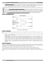
This function is used to change the operation of the digital input “DEN " so that when it goes to the logical level “0 " the drive can
disable itself (standard mode) or brake the motor (with or without ramp) until it stops and then disables.
If the DEN mode is set to "Drive Dis/Enab" (see section "
page 48), the “DEN " input is used to enable or disable
the drive and therefore it will stop for inertia. This is the standard mode.
Instead, if the DEN mode is set to “Drive Stop/Run ", the “DEN " input is used to start or stop the motor; in this case the motor will be
slowed down until it stops and then the drive disables and the motor is no longer powered (so it is free to move). If the speed ramp is
active (REN = ON), the motor slows down following the time set in the “Speed Ramp Time " parameter. If the speed ramp is NOT
active (REN = OFF) the motor slows down with the maximum available torque (emergency stop). For safety it is possible to set a
maximum time to stop the motor, after which the drive is disabled even if the motor is not stationary (menu “Motor Stop Time Max ").
To restart the motor, simply return the “DEN " command at the desired moments (if the RDY = 1). The motor will accelerate to the
reference speed.
5.6.7.2 Calibration
Normally this function is disabled and therefore the digital input “DEN " is used to enable and disable the drive; in this way the CNC
must reduce the speed reference to “0 " before removing DEN, otherwise the motor is no longer controlled and stops by inertia.
Instead, if you want to use the “DEN " input to drive and stop the motor without forcing the CNC to change the speed reference, you
can do this:
1. In the configuration menu “Advanced Setup → Aux Functions → Drive Stop/Run → Den Function ", select the mode:
“Drive Stop/Run ".
2. Set the “maximum time to stop motor ": go to the configuration menu “Advanced Setup → Aux Functions → Drive
Stop/Run → Motor Stop Time Max " and set the maximum time in seconds. This time is measured since the speed reference
(after any ramp) reaches the value “0 ". If within this time the motor is not stopped, the drive will disable automatically and
the motor stops by inertia.
5.6.8 Electronic gamma change
5.6.8.1 Generality
This function is used to change some parameters inside the drive when external switching of the motor windings takes place. A digital
input is used to control the switching of parameters inside the drive and the meaning is as follows:
•
Input = 0V (false): Switching on the set of parameters for slow range (Stage 0).
•
Input = 24V (true): Switching on the group of parameters for Fast Range (Stage 1).
If you have activated the sign reversal (see "Dig.Inp. X Sign“ on page 44), the above logical states should be reversed.
The parameters that will be switched when controlling the associated digital input are highlighted by an asterisk (*) in the Menu
structure page paragraph 21 and are listed in table 3 to page 69 where you can write the value of the modified parameter using the
menu.
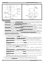
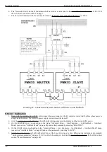
The drive also controls the actual switching of contactors; in the event that this does not happen, it signals an alarm on the LCD dis -
play and does not allow the motor to be enabled to avoid faults. To do this you need to connect a normally open contact of each con -
tactor (See drawing 25 and drawing 26) to a specific digital input of the drive and enable the control function in the "Check
Contactors“ menu.
Alter Elettronica s.r.l.
67


