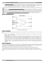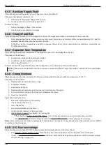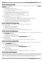
Commissioning
Instruction manual 91/104 V9.2
5.6.8.2 Calibration
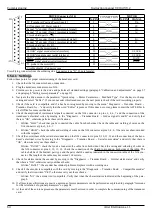
1. Set the digital input
to be used for switching the speed range: You should go to the "I/O Configure → Digital Inputs" menu
and from the destination selection menu on the desired input select the item "Stage bit 0" (see paragraph "Dig.Inp. X Dest“
on page 43). For safety it is better to check that there are no other inputs for this function.
2. Set the digital input
to use for slow range contactor control (Stage 0): You should go to the "I/O Configure → Digital Inputs"
menu and from the destination selection menu on the desired input select the item "Check STAGE 0" (see paragraph
"Dig.Inp. X Dest“ on page 43). For safety it is better to check that there are no other inputs for this function.
3. Set the digital input
to be used for fast range contactor control (Stage 1): You should go to the "I/O Configure → Digital In-
puts" menu and from the destination selection menu on the desired input select the item "Check STAGE 1" (see paragraph
"Dig.Inp. X Dest“ on page 43). For safety it is better to check that there are no other inputs for this function.
4. Set the digital output
to be used for the control of contactors that switch the motor windings. Use the "I/O Configure → Di-
gital Outputs" menu and from the source selection menu on the desired output select the item "Stage bit 0" (see paragraph
"Dig.Op. X source“ on page 44). For safety it is better to check that there are no other outputs intended for this function.
5. Enable the electronic gamma change function
with the menu: “Advanced Setup → Aux Function → Elec.Gear Change →
Stage Function ", set the parameter to “Enabled".
6. Check that the gamma change function is working properly:
•
Control the digital input to select the fast
range
parameters (see point 1).
•
Move to the “Advanced Setup → Aux Function → Elec.Gear Change → Selected Gear " menu and check for “Stage 1 ".
•
Check that the digital output
set to control the motor contactors (the one set in point 4) has the LED on and its logical
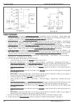
state is 1 (24Vcc present). Check that the quick range contactor is switched correctly (contactor S1 in drawing 26).
•
Check that the digital input
set to check the status of the fast range contactor has the LED on. This input has been set to
step 3.
•
Check that the digital input
set to check the status of the slow range contactor has the LED turned off. This input has
been set to step 2.
•
ATTENTION
: if the points listed above are not correct, check the electrical connections, settings or power supply of
contactors’ coils. If everything is in order you can continue with the test.
•
Control the digital input to select slow range parameters (see point 1).
•
Check on the menu “Advanced Setup → Aux Function → Elec.Gear Change → Selected Gear " that there is the words
“Stage 0 ".
•
Check that the digital output
set to control the motor contactors (the one set in point 4) has the LED off and its logical
state is 0 (floating output). Check that the slow range contactor is switched correctly (contactor S0 in drawing 26).
•
Check that the digital input
set to check the status of the fast range contactor has the LED turned off. This input has been
set to step 3.
•
Check that the digital input
set to check the status of the slow range contactor has the LED on. This input has been set to
step 2.
•
ATTENTION
: if the points listed above are not correct, check the electrical connections, settings or power supply of
contactors’ coils. If everything is in order you can continue with the test.
7. Keep the Slow Range (Stage 0) selected with the digital input and start the normal commissioning procedure.
8. Set the parameters and follow all the steps indicated in paragraph "Calibration and adjustments“ from page 57.
68
Alter Elettronica s.r.l.
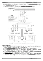
Drawing 25
Drawing 26

