Instruction manual 91/104 V9.2
Commissioning
5.6.10 JOG function
5.6.10.1 Generality
The JOG function is used to move the motor at a fixed or variable speed depending on a certain waveform. It is mainly used in ma-
chine tools to facilitate the grafting of the mechanical gearbox. In this function you can select 3 different types of Jog to be able to ad-
apt it to your needs.
The rating to the Jog function is done with a digital input that can be set at will; the DI2 input is set in standard configuration.
5.6.10.2 Calibration
These calibrations can be made with the drive enabled and the motor in rotation; however, it must be borne in mind that during the
changes of the following parameters, the motor may change its speed abruptly or reverse the direction.
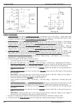
1. Set the digital input to use to enable the function (standard is already on DI2). See paragraph "Dig.Inp. X Dest“ on page 43.
If necessary, you can enable the function with the enabled drive to see the various movements.
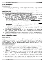
2. Move to the "Advanced Setup → Aux Functions → Jog Function → Jog Ref Mode" menu (paragraph "Jog ref. Mode“ on
page 51) and select the mode of generating the speed reference for the jog function. You can choose between:
•
FIXED REFER: When you enable the Jog function with the appropriate input, the motor rotates at a fixed speed. When
you disable the Jog function with the digital input, the motor “locks " the normal speed reference.
•
SQUARE WAVE: When you enable the Jog function with the input, the function generates a “Square Wave " with a
period and with an adjustable amplitude, so the motor rotates at the speed set for a certain time and then reverses the dir-
ection and turns backwards and continues in this way until the JOG command is removed.
•
TRIAN. WAVE: When you enable the Jog function with the selectable input (standard on DI2), the function generates a
“Triangular Wave " with an adjustable period and amplitude, so the motor accelerates gradually to the speed set with the
time set and then slows down gradually until you reverse the direction and reach the set speed (sign reverse). Then it
slows down again and continues like this until the JOG command is removed.
3. If the mode “Square Wave " or “Trian.Wave " has been selected in point 2, you can set the waveform period: Move to the
menu "Advanced Setup → Aux Functions → Jog Function → Jog Wave Time" (paragraph "Jog wave Time“ on page 51) and
write the period in seconds (with resolution to 1/10 sec).
4. Now you can change the rotation speed to the desired value, using the menu "Advanced Setup → Aux Functions → Jog
Function → Jog ref. Speed" (paragraph "Jog ref. Speed“ on page 51). This parameter can also vary while the motor is
spinning to see the result obtained.
NOTE:
It should be remembered that using the JOG function the motor moves without CNC or PLC control and the speed refer -
ence is generated within the drive according to a default function. For this reason you must always be careful not to do harm to the
machine or people during its use.
5.6.11 Anti-backlash system
5.6.11.1 Generality
The task of the electric anti backlash is to eliminate the mechanical play present in the kinematic chain when gearboxes and sprocket-
gear groups are used. The electric anti backlash uses two equal units, each consisting of a drive and an electric motor. The two drives
ensure that the torque generated by the two motors is equal but of the opposite sign. In this way the gear teeth are in contact and the
kinematic chain plays are cancelled. When the system is in motion the torque dispensed by one motor increases while that of the other
diminishes keeping the play of the kinematic chain always null. The anti-backlash system uses two equal drives (same rated current).
One drive is called
Master
and the other
Slave
. The
Master drive
receives all the controls from the outside and controls the system
while the
Slave
drive is driven by the
Master.
5.6.11.2 Connection diagram
1. Follow the connection scheme of Drawing 1 on page 11 (for THREE-PHASE power supply) or as indicated in Drawing 2 on
page 12 (for DC BUS D.C. power supply) with regard to the connection of the motor, the transducer, the power supply
auxiliary services and possibly the external braking resistance for both the MASTER drive and the SLAVE drive.
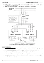
2. For links specific to the anti-backlash system, please follow Drawing 22 on page 56. All commands and signals coming from
the CNC or PLC must be connected exclusively to the MASTER drive. The DOK and RDY signals must be used in the
MASTER drive.
3. Connect DC+ and DC- of the MASTER drive with the corresponding DC+ and DC- of the SLAVE drive, as shown in
Drawing 22 on page 56. In the case of three-phase power supply the power cables must be connected to the L1-L2-L3
terminals as indicated in the drawing, in the case of direct power supply on the DC-BUS these terminals must remain empty.
4. Connect the MASTER and SLAVE drives with a twisted cable inserted on the X7 connectors of the two drives, as indicated
5. Fuse backhoes indicated with F2 and F3 should be sized following Table 2 on page 7 (with “ultra rapid” fuses). The fuse tern
indicated with F1 must be sized to protect cables from overload (no need for “ultra rapid” fuses).
Alter Elettronica s.r.l.
71


