Commissioning
Instruction manual 91/104 V9.2
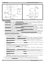
If the motor is to be rotated again, the “Spindle Lock " control shall be removed and the speed reference shall be brought
to the required value.
NOTE:
This function uses the space loop of the positioner function (see paragraph 5.6.13) then the parameters "Proport.Gain"
and "Integr. Gain’s the same. If the input associated with the “Spindle Lock " function and the one associated with “Position En-
able " are activated at the same time, priority is given to the positioner function.
5.6.13 Positioner
5.6.13.1 Generality
This function is used to control (with a digital input) the positioning of the motor in 4 different positions that can be selected with a
combination of digital inputs.
For this function it is necessary to use a position transducer with zero reference signal (Z channel), or a resolver: positioning cannot be
performed with an encoder provided with only incremental channels A and B.
If the drive is enabled (DEN = ON) and this command is provided, the drive slows the motor down to the “positioning speed" using
the set ramp, if it is active (REN=ON), and then moves the motor shaft to the selected position, activating a position loop that keeps
the motor locked.
When the motor shaft has reached the set position and is stationary, the signal of “Reached Position " is indicated on a specific digital
output that can be set.
The positioning control (POSITION ENABLE = OFF) must be removed to restart the motor when it is not necessary to keep it in
position: The motor will accelerate to the reference speed using the set ramp, if it is active (REN=ON).
5.6.13.2 Calibration
1. Set the digital input
to use for the “Position Enable " command. Normally digital input 4 (DI4) is already associated to per -
form this function. You can check if this is true by going to the "I/O Configure → Digital Inputs" menu and from the destina -
tion selection menu on the desired input select the item "Posit. Enable“ (see paragraph "Dig.Inp. X Dest“ on page 43). If you
want to change the logical state of command to activate the function, you must enter (or disconnect) the logical reversal set -
ting of the input (see paragraph "Dig.Inp. X Sign“ on page 44). For safety it is better to check that there are no other inputs
for this function.
2. If there is a need to have more than one working position, you must set the digital inputs to
use to select one of the 4 positions. If the necessary positions are only 2, you can use a di -
gital input, otherwise 2 digital inputs are needed. To set the digital inputs to be used you can
go to the "I/O Configure → Digital Inputs" menu and from the destination selection menu on
the desired input select "Posit. Bit0“ or "Posit. Bit1“ (see paragraph "Dig.Inp. X Dest“ on
page 43). If you want to change the logical state of command to activate the function, you
must enter (or disconnect) the logical reversal setting of the input (see paragraph "Dig.Inp. X
Sign“ on page 44). For safety it is better to check that there are no other inputs for this func-
tion. The table on the side shows the combination of BIT 0 and BIT 1 to select the position -
ing quota.
BIT
1
BIT
0
POSITION
0
0
Position 0
0
1
Position 1
1
0
Position 2
1
1
Position 3
3. Set the digital signal output
“Position Reached" (if needed); the DO4 digital output is normally already set. To check, go to
the configuration menu "I/O Configure → Digital Outputs" and from the selection menu of the source of the desired output
go to check the item "Position Reach" (see paragraph "Dig.Op. X source“ on page 44). If you want to change the logical state
of the output when the motor is in position, you must insert (or disconnect) the logical reversal setting of the output (see
paragraph "Dig.Op. X Sign“ on page 45).
4. Setting up positions
:
Enable the drive (DEN = ON) and give a speed reference so that the motor shaft rotates.
Select “Position 0 "
. This is done using the combination of the two inputs set in point 2. If only one position is used, the
two inputs should be left unconnected or set to do other functions.
Enable positioning (POSITION ENABLE = ON).
The motor must slow down and then stop in the selected position without commutes or vibrations. If the motor is un -
stable, the proportional gain of the position loop must be reduced from the configuration menu “Advanced Setup → Aux
Functions → Position Loop → Proport Gain".
Remove and place the positioning command (POSITION ENABLE) for a few times until a good response is obtained.
At this point, keeping positioning enabled (POSITION ENABLE = ON), go to the configuration menu “Advanced Setup
→ Aux Functions → Position Loop → Position 0" and change the position until you move the spindle to the desired pos-
ition as “Position 0".
If there are other locations to store, you have to change the combination of the two digital inputs set to step 2 and then
repeat the procedure as indicated in the previous step until you set all the necessary positions.
At the end disable the drive (DEN = OFF) and save the parameters in the Flash memory.
74
Alter Elettronica s.r.l.

