Board Reference
Type
Description
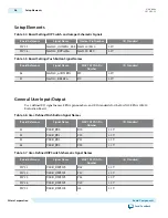
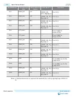
S1, S2, S3, S4
User push buttons
Four user push buttons. Driven low when
pressed.
D3, D4, D5, D6, D7
User LEDs, green
Five user LEDs. Illuminate when driven
low.
SW1, SW2.1, SW2.2
User DIP switches
Quad user DIP switches.
Memory Devices
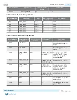
U2
LPDDR2 SDRAM memory
64 M x16
U23
Quad serial peripheral
interface (quad SPI) flash
512 Mb
Video and Display Ports
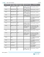
J1
MIPI CSI-2 transmitter output MIPI CSI-2 transmitter output to Leopard
Imaging LI-MIPI-USB3-Tester module.
J2
MIPI CSI-2 receiver
MIPI CSI-2 receiver input from Leopard
Imaging LI-CAM-OV10640-MIPI module.
J3
MIPI CSI-2 receiver
MIPI CSI-2 receiver input from UDOO
Camera Module OV5640.
J4
HDMI video output
19-pin HDMI connector which provides a
HDMIv1.4 video output of up to 1080p
through an ADI (Analog Devices, Inc)
HDMI transmitter (ADV7513).
I/O and Expansion Ports
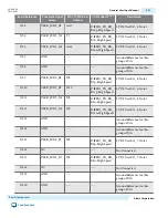
J8, J9
Two Diligent Pmod connectors 12-pin interface with 8 I/O signal pins used
to connect low frequency, low I/O
peripheral modules.
J12, J13
Two 2x10 GPIO connectors,
user install
You can use this area to connect or solder
additional components for connection of 9
true LVDS pairs with clock input and
output, or 22 single-ended I/O signals.
J14
2x7 GPIO connectors, user
install
You can use this area to connect or solder
additional components for connection of
10 single-ended I/O signals.
Power Supply
J10
DC input jack
Accepts 5V DC power supply when USB
power supply is not in use.
SW3
Power switch
When using DC power adapter, switch to
power on or off the board when power is
supplied from the DC input jack. DC
adapter and USB power don't work at the
same time.
UG-20006
2016.02.29
Board Overview
3-5
Board Components
Altera Corporation
Send Feedback


