13
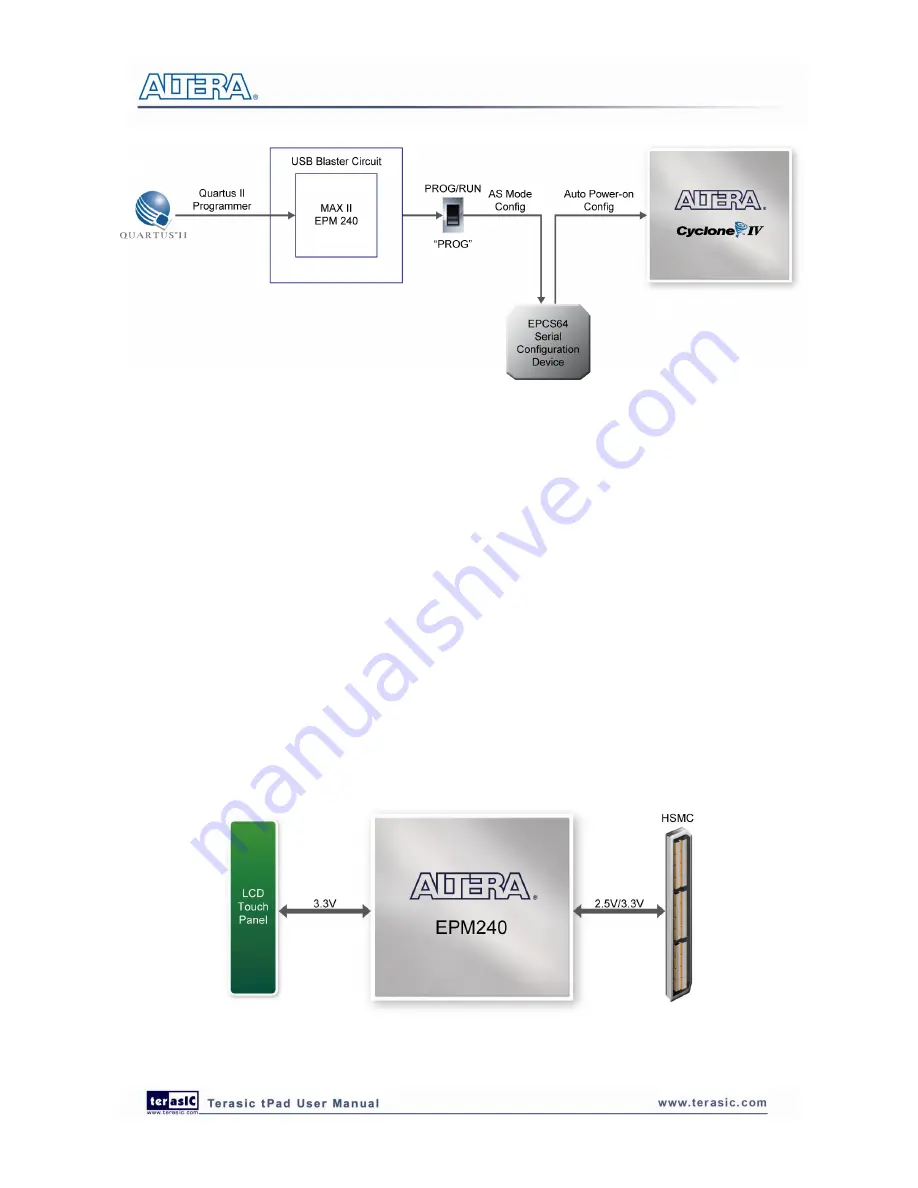
Figure 3-5 The AS configuration scheme
3
3
.
.
2
2
B
B
u
u
s
s
C
C
o
o
n
n
t
t
r
r
o
o
l
l
l
l
e
e
r
r
The tPad comes with a bus controller using the Max II EPM240 that allows user to access the touch
screen module through the HSMC connector. This section describes its structure in block diagram
form and its capabilities.
Bus Controller Introduction
The bus controller provides level shifting functionality from 2.5V (HSMC) to 3.3V domains.
Block Diagram of the Bus Controller
Figure 3-6
gives the block diagram of the connection setup from the HSMC connector to the bus
controller on the Max II EPM240 to the touch screen module. To provide maximum flexibility for
the user, all connections are established through the HSMC connector. Thus, the user can configure
the Cyclone IV E FPGA on the tPad to implement any system design.
Figure 3-6 Block Diagram of the Bus Controller


