The Quartus II software automatically generates MIF for all designs that support POF generation with the
following exceptions:
• Designs that use bonded channels so that the same TX PLL output drives several channels
• GT channels
• Non-bonded channels in a design that also includes bonded channels
MIF Format
The MIF file is organized into records where each record contains the information necessary to carry out
the reconfiguration process.
There are two types of records: non-data records and data records. A MIF can contain a variable number
of records, depending on the target transceiver channel. Both data records and non-data records are 16-
bits long.
For both record types the high-order 5 bits represent the
length
field. A
length
field of 5’b0, indicates a
non-data record which contains an opcode. A length field that is not zero indicates a data record.
For a non-data record, the opcode is represented by the lower 5-bits in the record.
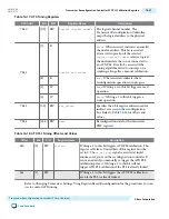
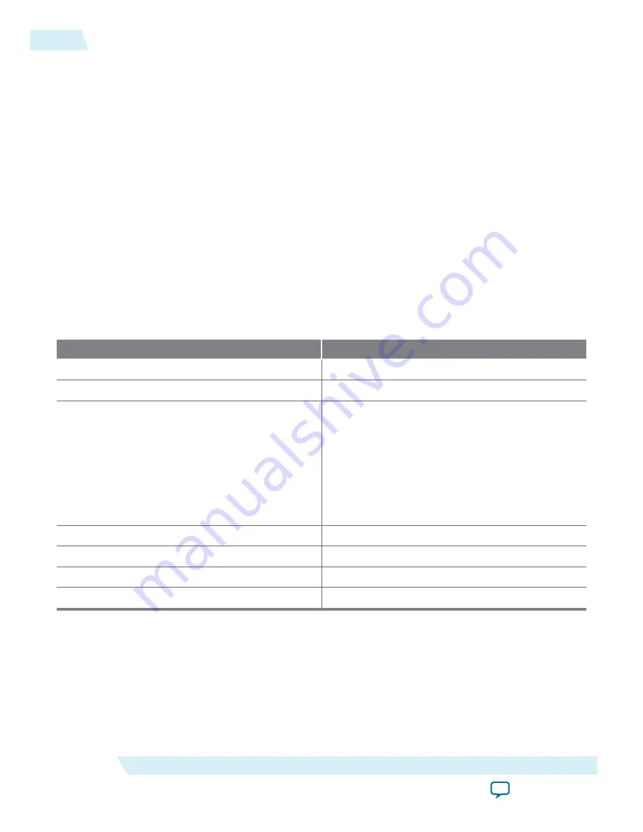
Table 16-26: Opcodes for MIF Files
Opcode
Opcode Description
5’b00000
Reserved
5’b00001
Start of MIF
5’b00010
Channel format indicator specifying the MIF
channel type. The following encodings are defined:
• 3’b000: Duplex channel
• 3’b001: TX PLL (CMU)
• 3’b010: RX only channel
• 3’b011: TX only channel
• 3’b100: TX PLL (ATX)
5’b00011
Reference Clock switch
5’b00100
CGB switch
5’b00101-5’b11110
Reserved
5’b11111
End of MIF (EOM)
For data records, the low-order 11 bits provide a logical offset address. In this case, the length field
indicates the number of data records that are written into the specified address. For example, if the length
field is set to two, the next two records belong the data record and are written into the offset address.
All MIF files must contain the lines in the following table.
16-38
MIF Format
UG-01080
2015.01.19
Altera Corporation
Transceiver Reconfiguration Controller IP Core Overview
Send Feedback


