DXR Drainback
Page 10
MOUNTING HARDWARE SPACING
Solar Collector Dimensions
Model
No. AE-21 AE-24 AE-26 AE-28 AE-32 AE-40 MSC-21 MSC-24 MSC-26 MSC-28 MSC-32 MSC-40
Length (l)
85.187
97.187
77.187
85.187
97.187
121.187 86.125 98.125 78.125 86.125 98.125 122.125
Width (w)
35.187
35.187
47.187
47.187
47.187
47.187 35.875 35.875 47.875 47.875 47.875 47.875
Height (h)
3.137
3.137
3.137
3.137
3.137
3.137 3.082 3.082 3.082 3.082 3.082 3.082
Area
20.82
23.75
25.29
27.91
31.85
39.71 21.46 24.45 25.97 28.63 32.62 40.60
Weight
74 84 90 99 113 153 76
87
91 102 116 151
MOUNTING HARDWARE SPACING – Centerline to Centerline (in)
AE-MH
MSC-MH
86.187 98.187 78.187 86.187 98.187 122.187 88.233 100.233 80.233
88.233 100.233 124.233
AE-FM
MSC-RRM
88.663
100.663
80.663
88.663
100.663
122.663 87.375 99.375 79.375 87.375 99.375 12.375
AE-RM
MSC-RM
86.835
98.835
78.835
86.835
98.835
122.835 87.333 99.333 79.333 87.333 99.333 123.333
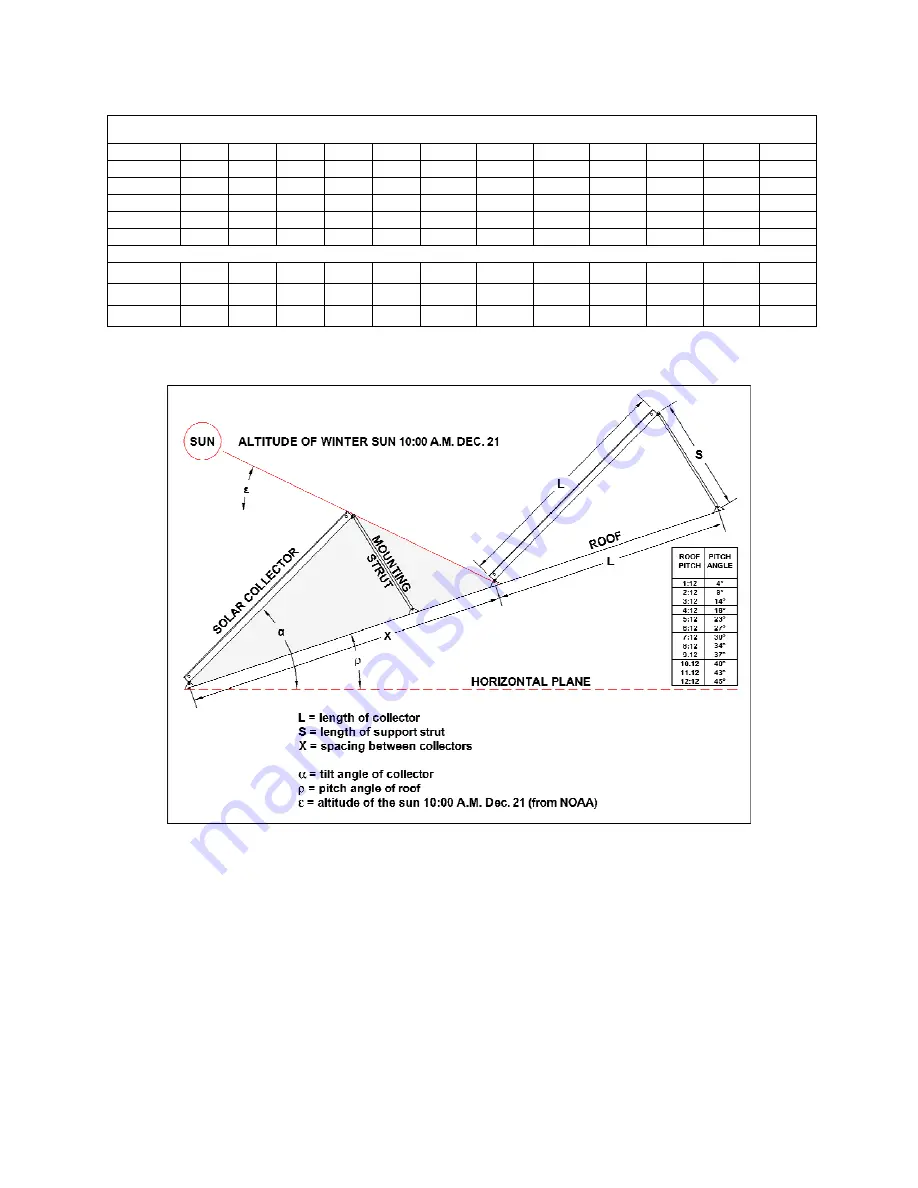
Dimensions shown (length, width and height) are nominal and listed in inches, area in ft² and weight in lbs. Use the formulas below for tilted applications.
To calculate the length of the support strut use the formula as follows:
S = 2 x L x sin((
α
–
ρ
) ÷ 2)
Add two (2) inches to the calculated length to allow for the pre-drilled holes, positioned ± 1.0 in from each end of
the support strut.
To calculate the recommended spacing between collectors use the formula as follows:
X = L x cos(
α
–
ρ
) + L x sin(
α
–
ρ
) x tan(90 –
ρ
–
ε
)
This would be spacing distance required to insure collectors do not shade one another in stacked arrays or saw-tooth
type mounting configurations.


