background image


TAEC Solar Box 

Owner’s Manual

 v2.2 


1.


Introduction 


All Energie 

 Thermodynamic Solar Systems products are to be kept in the original packaging and 

should be stored or transported in the upright position - note there is an arrow to indicate the 

‘Up’ direction for 

panel and the Solar Box. 

The Solar Box compressor, contains oil and must not be tipped over at any stage


The Solar Box system design is based on the Carnot thermodynamic cycle, the principle of 
evaporation, compression and condensation and expansion.  The Solar Box has an additional 
solar gain achieved by the solar panel. 
 
The solar panel should be placed outside to capture heat from solar radiation, but also from the 
atmospheric conditions such as wind and rain etc 
The refrigerant enters the panel as a cold liquid.  The temperature difference between the 
refrigerant gas and the temperature of the panel ensures that the refrigerant fluid evaporates 
and leaves the panel as a gas.  The gas is compressed by the compressor, which further raises the 
temperature.  The heat is then transmitted to the water circuit via a heat exchanger.  The gas 
then passes through an expansion valve, becoming liquid again, completing the overall cycle. 
As the temperature of the solar panel increases from the sun, the efficiency of the system is 
greatly improved. 


In this process, we use technology and the environment to generate the power to heat all your 
water all year round. 


The refrigeration gas used in the Solar Box system is R134a.  This is CFC free, is non-inflammable 
and does not harm the ozone layer; 


The system comes preloaded with the required refrigerant gas.  No additional gas should 
be required for the installation. 


Legally, in New Zealand the refrigerant in this system cannot be released into the 
environment. 


Handling of the refrigerant must be carried out by an approved refrigeration technician. 


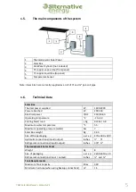
Thermodynamic Solar Panel 


Panel mounting brackets, and bolts 


Panel roof mounting kit 


Certified Top-hat roof penetration kit 


Solar Box unit 


Water connections including 

“Y” 

strainer 


1.1.


Packing, Storage & Transportation 

1.2.


Description 

1.3.


Refrigeration gas 

1.4.


Components 

Summary of Contents for Energie Solar Box

Page 1: ...olar System Solar Box Suitable for use with mains pressure systems Discover the Power of Thermodynamic Solar Energy This Owner s Manual must be read carefully and followed to ensure the proper operation and maximum efficiency of the equipment ...

Page 2: ...gerant gas used is R134a a free of CFCs non inflammable and harmless to the ozone layer but it must not be released into the atmosphere by law Please read the following instructions before any installation works or operation of the solar system proceed The Thermodynamic Solar Box shall only be used for the heating of fresh water only to temperature limits indicated The technical rules see DIN 1988...

Page 3: ...ation gas 4 1 4 Components 4 1 5 The main components of the system 5 1 6 Technical Data 5 1 7 Dimensions 6 1 8 Solar Panel 6 2 Control Panel 7 2 1 Initial start up 7 2 2 Control Panel Functions 8 2 3 Installer Menu parameters 9 3 Fault finding Problem solving 11 4 Wiring Diagram 13 4 1 Input Output specifications 14 5 Guarantee 15 ...

Page 4: ...ressed by the compressor which further raises the temperature The heat is then transmitted to the water circuit via a heat exchanger The gas then passes through an expansion valve becoming liquid again completing the overall cycle As the temperature of the solar panel increases from the sun the efficiency of the system is greatly improved In this process we use technology and the environment to ge...

Page 5: ...perature o 2 2 to 42 Cooling fluid load Kg R134a 0 8 Maximum water temperature o C 55 Maximum operating pressure water bar 7 Solar Box weight Kg 23 5 Size of the packaging a x I x p 470 x 400 x 400 Hydraulic connections input output inches Refrigerant connections input output inches 3 8 Thermodynamic Solar Panel Weight Kg 8 Size of packaging a x I x p 2200 x 810 x 30 Refrigerant connections input ...

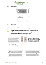
Page 6: ... with its 2000mm length horizontal and the 800mm side vertical The panel must not be mounted flat It must be on an angle greater than 10 to ensure separation between the vapour from the liquid The pipe connections must be facing down with the liquid line at the bottom Panels can be supplied as left or right according to side of the panel the connections are located with the pipes pointing down the...

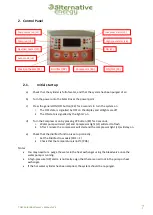
Page 7: ...start to flash ii After 1 minute the compressor will start and the compressor light L1 will stay on e Check that the disinfect function is set up correctly i Set the Disinfect to weekly CO1 1 ii Check that the temperature is 60 C PO5 Notes You may need to re purge the water in the heat exchanger using the bleed valve once the water pump is running A high pressure HP alarm is normally a sign that t...

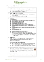
Page 8: ...lay shows the probe temperature S1 Main display on temperature probe damage or alarm signal o Lo out of range to the low temperature under 0o C Probe broken o Hi out of range to the high temperature over 100o C Probe in short circuit 4 Auto function When the Auto mode is activated the electrical heater is automatically activated deactivated when the temperature is below the Auto Temperature Set Po...

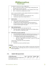
Page 9: ...tarts again 8 Pump anti block Function If the pump is OFF for a time over Anti block Timer T04 The output PUMP is activated for T05 seconds and the display shows bLP The function is enabled also in OFF 9 Installer Menu to change parameters Enter the MENU pushing together K1 and K4 buttons for about 5 seconds Scroll and visualise the parameters code through K3 or K2 buttons Visualise the parameters...

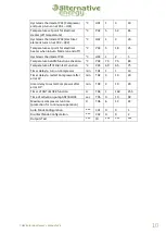
Page 10: ...rmostat P03 C H03 1 2 5 Temperature ALARM function activation C P04 70 75 80 Temperature off of Disinfect Function C P05 60 65 75 Timer delay to turn on Compressor min T01 1 1 10 Timer delay to restart Compressor after error LP min T02 3 10 20 timer delay to restart Compressor after error HP min T03 3 10 20 Timer of ANTI BLOCK function H T04 1 168 255 Time of activation pump ANTI BLOCK sec T05 0 1...

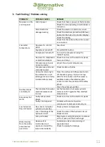
Page 11: ...safety valve Close the cold water inflow valve to turn off the safety group Open a hot tap Wait for 10 minutes and if hot water is available replace the defective pipe and or correct the position of the safety group Clean the safety group filter Disinfect mode constantly on Thermostat of hot water electrical element set too low Set thermostat on hot water cylinder element to 70 C greater than disi...

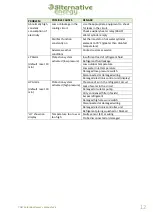
Page 12: ... activated low pressure Insufficient load of refrigerant fluid Refrigerant fluid leakage Low outdoor temperature Low water inlet temperature Damaged low pressure switch Disconnected or damaged wiring Damaged electronic control unit display HP Alarm default reset 10 min Protection system activated high pressure Presence of air in the refrigerant circuit Lack of water in the circuit Damaged circulat...

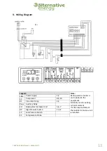
Page 13: ...ment Normally use the existing cylinder element It is the responsibility of the installer to make sure it is installed LINE Power supply 1 2 CP Compressor 8 9 10 B1 Circulator Pump 3 4 Raux Auxiliary Relay EH Backup Electric Heater Coil 5 6 7 HP High Pressure Switch 11 12 LP Low Pressure Switch S1 Temperature Probe REL ...

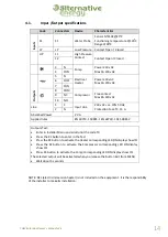
Page 14: ...A 2 N Absorbed Power 2 VA Applied rules EN 60730 1 50081 1 EN 60730 1 A1 50081 2 Outputs Test Enter in Installer Menu and scroll until the code T0 Press the K1 button to enter in the Test Press the K1 button to activate the Heater corresponding LED ON display show tSt Press the K2 button to activate the Compressor corresponding LED ON display show tSt Press K3 button to activate the Pump correspon...

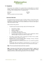
Page 15: ...l Inox Hardness 200 mg l Conductibility 600 mS cm 20o C 5 5 PH and PH 9 Sorensen scale at 20o C If one of the water parameters has a greater value than stipulated by directive 236 98 Portugal or equivalent star dint eh customers county o Parts subject to natural wear and tear including but not limited to levers switches resistors programmers thermostats anode etc o Breakdown due to incorrect handl...

Reviews: