background image

                                                         MULTI-TASKER

1

                       TABLE OF CONTENTS

                                                                             Page

PRECAUTIONS / SAFETY WARNINGS .............. 2

1.1 GENERAL ................................ .................. 2

1.2 INSTALLATION ................................ .......... 2

1.3 CLEANING ................................ ................. 2

1.4 FCC / CE NOTICE................................ ...... 2

ABOUT YOUR MT108-104/(105)......................... 3

TECHNICAL SPECIFICATIONS .......................... 3

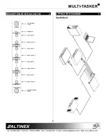
DESCRIPTION OF MT108-104/(105).................. 4

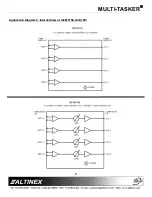
APPLICATION DIAGRAM................................ .... 4

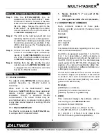
INSTALLING YOUR MT108-104/(105)................ 6

OPERATION................................ ........................ 6

7.1  RS-232 CONTROL................................ .... 6

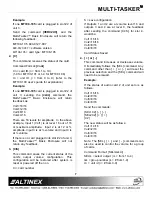
7.2  DESCRIPTION OF COMMANDS .............. 6

7.3  SUMMARY OF COMMANDS..................... 9

TROUBLESHOOTING GUIDE............................. 9

8.1  LED IS NOT LIT ................................ ........ 9

8.2  NO SOUND ................................ ............... 9

8.3  SOUND DISTORTION............................. 10

8.4  SOUND LEVEL IS LOW.......................... 10

ALTINEX POLICY................................ .............. 10

Summary of Contents for MULTI-TASKER MT108-104

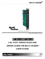
Page 1: ...MULTI TASKER MANUAL PART NUMBER 400 0178 002 MT108 104 MT108 105 4 IN 4 OUT STEREO AUDIO LINE DRIVER CARDS FOR MULTI TASKER USER S GUIDE TM MT108 104 is shown above...

Page 2: ...MT108 104 105 3 TECHNICAL SPECIFICATIONS 3 DESCRIPTION OF MT108 104 105 4 APPLICATION DIAGRAM 4 INSTALLING YOUR MT108 104 105 6 OPERATION 6 7 1 RS 232 CONTROL 6 7 2 DESCRIPTION OF COMMANDS 6 7 3 SUMM...

Page 3: ...ly the connector area with a dry cloth Never use strong detergents or solvents such as alcohol or thinner Do not use a wet cloth or water to clean the card Do not clean or touch any component or PCB 1...

Page 4: ...r on the card is a red LED indicating the board has power applied These cards consume one slot each TECHNICAL SPECIFICATIONS 3 FEATURES DESCRIPTION MT108 104 105 GENERAL Inputs 4 Input Connector Four...

Page 5: ...MULTI TASKER 4 DESCRIPTION OF MT108 104 105 4 APPLICATION DIAGRAM 5 Application 1...

Page 6: ...MULTI TASKER 5 Application Diagram 2 Internal View of the MT108 104 105...

Page 7: ...control may be accomplished using a computer control system or any other device capable of sending RS 232 commands 7 1 1 RS 232 INTERFACE The RS 232 commands for the MT108 105 are in a simple ASCII ch...

Page 8: ...t 2 of unit 3 the Multi Tasker Basic Enclosure will not return any feedback 3 CiS This command saves the current status of the card s output volume configuration This configuration will be restored af...

Page 9: ...d VOL1A16C4 will set the volume of output 1 to the maximum level of 16 7 CLR Card The command clears all volumes to maximum for a single card With this command 200ms is needed for execution Insert a 2...

Page 10: ...d MT108 104 105 however we would like to offer suggestions for the following 8 1 LED IS NOT LIT 8 2 NO SOUND 8 3 SOUND DISTORTION 8 4 SOUND LEVEL IS LOW 8 1 LED IS NOT LIT Cause 1 Card cage is not plu...

Page 11: ...tion amplifier provides excessive amplification Solution 1 Make sure that the source level is high enough so the destination amp does not have to provide excessive amplification thereby distorting the...

Reviews: