background image

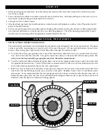
S T A R T - U P

1.  Before operating the merchandiser, clean the interior and exterior of the unit with a damp cloth and mild soap solu-

tion.  Rinse carefully.

2.  Clean and install the cabinet wire shelves inside the hot and cold cavities,  the bottom baffle pan in the hot cavity, and

the external condensate drip pan underneath the cold cavity.

3.  Clean glass with a window cleaner.

4.  After final hook-up, locate the circuit breaker box under the unit and flip breaker switches to the ON position for full

power to the merchandiser.

5.  Let the case run through at least one defrost before loading with product, checking the duration of defrost (preferably

two or more) and frequency, to make sure the case is defrosting properly.  Check the operating temperature to make
sure the case is functioning within the guidelines recommended for this case.

O P E R A T I O N A L   P R O C E D U R E S

1.

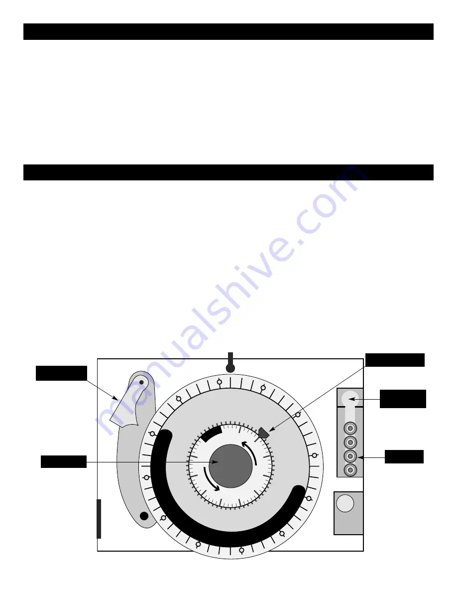
SETTING TIMER / DEFROST MECHANISM.

The timer/defrost mechanism is located behind the end panel on the refrigerated side of the merchandiser.  The panel

can be removed by unscrewing two screws located at the top of the panel.  Lift up and slide bottom of panel out to
remove.  Press spring clip at right center of timer defrost box and open the metal case door. 

A. To set the time of day, grasp knob in the center of the inner 2-hour dial and rotate it in a counter-clockwise direc-

tion.  This will revolve the outer dial.  Line up the correct time of day on the outer dial with the time pointer.  

Do

not try to set the time control by grasping the outer dial.  Rotate the inner dial only.

B. To set the mechanical defrost termination, push down and rotate the copper pointer on the inside 2-hour dial until

it is opposite the desired time.  Twenty (20) minutes is recommended in order to avoid frost build-up on the coils
and avoids warming of products kept in the cold compartment.

C. Slide the screw start pins out of the holder on the right side and place the start pins in the outer 24-hour dial at the

time of day that the defrosting should occur, and screw into place.  

Caution:  

Leave at least 1 hole between each

adjacent pin.  It is recommended that the start pins be placed every 6 hours to coincide with off-peak times such as
before the store opens, after the store closes and lull periods during the business day to prevent the excess loss of
chilled air when the doors are continuously being opened.

Operation & Care Manual #843 • 2.

1

2

3

4

5

6

7

8

9

10

11

MID

1

2

3

4

5

6

7

8

9

10

11

NOO

N


T

I M

E

11

0

2

10

20

3

0

4

0

50

60

70

80

9

0

1

0

0

T

U

R

N

KN

OB

T

U

R

N

KN

OB

MID

NIG

HT

Copper Pointer

r

Time Pointer

Inner Dial

Start Pin

Holder

Start Pin

Summary of Contents for 1000-HCM

Page 1: ...4 N 9 2 2 1 W a t e r S t r e e t P O B o x 4 5 0 M e n o m o n e e F a l l s W i s c o n s i n 5 3 0 5 2 0 4 5 0 U S A PHONE 262 251 3800 FAX 262 251 7067 800 329 8744 U S A ONLY WEBSITE 800 558 874...

Page 2: ...culation Refer to counter layout in this manual NOTE Any claims for warranty must include the full model number and serial number of the cabinet H A R A C T ENSURE POWER SOURCE MATCHES VOLTAGE STAMPED...

Page 3: ...he metal case door A To set the time of day grasp knob in the center of the inner 2 hour dial and rotate it in a counter clockwise direc tion This will revolve the outer dial Line up the correct time...

Page 4: ...or five seconds Holding the SET button allows the programming mode to become active L E D Display The L E D display will show the set point temperature value when programming or the warm or cold chamb...

Page 5: ...product It is advisable to periodically check the internal tempera ture of each item to assure maintenance of proper food serving temperature F CHAMBER TEMPERATURE L E D L E D 1 200 SET CAUTION The un...

Page 6: ...it is advisable to periodically check the internal temperature of each item with a food ther mometer to assure maintenance of the proper temperature range of 150 to 160 F 66 to 71 C 4 WHEN NOT IN USE...

Page 7: ...t Holding Equipment is provided with a ther mostat control between 60 and 200 F 16 to 93 C If the unit is equipped with vents close the vents for moist holding and open the vents for crisp holding H O...

Page 8: ...water or commer cial detergent 6 To help maintain the protecive film coating on pol ished stainless steel clean the exterior of the cabi net with a cleaner recommended for stainless steel surfaces Spr...

Page 9: ...UG NET WEIGHT 610 lb 264 kg SHIP WEIGHT 930 lb 366 kg OPTIONS Color Match Side Panels FACTORY QUOTE ACCESSORIES Customized Signage 66 1 4 W x 7 1 4 H 1682mm X 184mm FACTORY QUOTE Meal Express Graphic...

Page 10: ...s at the thermostat and terminal block If necessary re secure the faulty connections Energize system after the above steps have been completed If control still reads CCC contact factory Check power so...

Page 11: ...TRONIC TT 33563 30 TERMINAL BLOCK UPPER BK 3023 31 SENSOR 2 SN 33541 SENSOR TERMINAL BLOCK BK 33546 32 PLASTIC DECOR SIGN ENDS 4 GL 23442 33 MENU BOARD NOT SHOWN 1 MB 22976 34 DECOR STRIP ASSEMBLY 1 1...

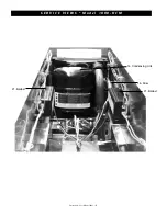
Page 12: ...Operation Care Manual 843 11 S E R V I C E V I E W S M o d e l 1 0 0 0 H C M 17 Defrost clock 23 Cordset 26 Main power switch 28 Transformer 27 Relay 28 Transformer 39 Fuses holders for ballast...

Page 13: ...Operation Care Manual 843 12 S E R V I C E V I E W S M o d e l 1 0 0 0 H C M 21 Ballast 14 Condensing Unit 15 Drier 21 Ballast...

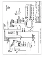
Page 14: ...Operation Care Manual 843 13...

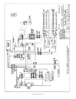
Page 15: ...Operation Care Manual 843 14...

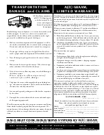
Page 16: ...rst Exceptions to the one year part warranty period are as listed A Halo Heat cook hold ovens include a five 5 year parts warranty on the heating element Labor will be covered under the terms of the s...

Reviews: