background image

p a r t S   i N f o r m a t i o N

C

o m m o n

  P

a r t s

  •  C

o m b i t h e r m

  e

l e C t r i C

  t

e C h n i C a l

  S

e r v i C e

  m

a n u a l

  •  e–

4

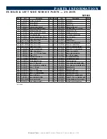
E S   r E a r   &   L E f t   S i d E   S E r V i C E   p a r t S   —   2 0 . 2 0 E S

A

46

51

40

19

17

13

43

53

41

27

7

12

16

21

25

25

29

28

20

27

37

14

38

7

34

60

35 55 44 57

6

30

25

45 57 55

5

32 58 56

28

28

49

28

28

29

11

16

52

10

20

25

12

27

24

27

18

49

18

27

22

27

23

22

28

53

31 47

50

31 47 54 14

6

10

7

13

14

14 36

11

15

8

39 43

27

13 19

1

38

14

37

Left Side View

Rear View

Plumping

Detail A

Summary of Contents for CombiTouch 7.14es

Page 1: ...Technical Service Manual ...

Page 2: ...ns the special programming available to you as a technician to view status make adjustments and test functions on models equipped with Standard and Deluxe Controllers Information is also included on the use of displayed error codes to resolve problems and on the functions that can be operated under fault conditions TROUBLESHOOTING TREES are provided for the most common conditions you will be requi...

Page 3: ...c e Ma n u a l ii Table of Contents Table of Contents How to Use this Technical Service Manual i Introduction iii Control Panel Identification A 1 Preventive Maintenance B 1 Service Mode and Error Codes C 1 Troubleshooting Trees D 1 Combitherm Parts E 1 Wire Diagrams F 1 ...

Page 4: ...dels FEATURES AND OPTIONS Recessed Door is available on all models Left hand door is available on countertop models Smoker Mode is available on select boiler free models Introduction Steam Generator Models Boiler Free Models Narrow Boiler Free Models 6 10ES 10 10ES 7 14ES 10 18ES 12 20ES 20 20ES 6 10ESi 10 10ESi 7 14ESi 10 18ESi 20 20ESi 6 10ESiN 10 10ESiN ...

Page 5: ... h n i c a l Se r v i c e Ma n u a l A 1 Introduction A 2 Start up Procedures A 3 Control Panel Identification A 4 Factory Default Settings A 8 Change Temperature Settings A 8 Safety Precautions A 9 HACCP Access A 10 Return to Main Table of Contents ii To u ch Co ntrol Identification Introduction ...

Page 6: ...ent baking results A moisture injection feature provides perfect sheen and crust on breads and pastry items Multi shelf timers Track cooking time of either 7 or 10 different food items depending on oven size in the same oven with multi shelf timers Time is tracked in minutes and seconds On board diagnostics The CombiTouch system includes on board diagnostic functionality with results displayed rig...

Page 7: ...process the operator will be prompted to calibrate the CombiTouch screen when the oven is next powered up see illustration 3 at left Return to Recipe Menu Press the red arrow if the CombiTouch screen does not need to be calibrated Begin Calibration Process Press the green check mark if the CombiTouch screen does need to be calibrated The screen will switch to a grey background see illustration 4 a...

Page 8: ...nformation 4 Service Mode password protected This mode is only available to qualified service technicians 1 Download Recipes Copy all recipes from USB memory stick to oven This will replace and overwrite existing recipes 2 Upload Recipes Copy all recipes from oven to USB memory stick 3 Add All Recipes Copy all recipes from USB memory stick to the oven This will add the recipes to the beginning of ...

Page 9: ...dual shelf time settings for each shelf 5 Default Memo Left icon reverts time temperature setting to factory defaults when switching modes Right icon allows you to keep the last user setting 6 Display Settings Choose to display text or image assigned to a recipe 7 Return to Previous Screen Return to previous screen when finished adjusting settings 8 Forward to Next Screen Advance to next screen to...

Page 10: ...1 Power ON key 2 Steam mode 6 Temperature 7 Time 8 core Temperature 9 preheat 12 reduced Power mode 16 go to Previous Screen 10 cool down 15 fan speed 20 Multi shelf timer 19 find recipe 17 cleaning mode 18 add recipe 11 start stop icon 13 gold n brown mode 4 Convection mode 5 retherm mode 3 combination mode 14 smoking mode optional 22 Delta T only visible in certain modes 1 Power OFF key ...

Page 11: ...o a temperature set by user 10 Cool Down Mode Lowers temperature of the oven cavity at an accelerated pace to temperature set by user 11 Start Stop Initiates all cooking mode functions and programmed procedures stored in memory Stops an activated cooking mode or programmed procedure currently in progress auxiliary function Icons 12 Reduced Power Mode Used to reduce kitchen power peaks and energy c...

Page 12: ...0 C 25 minutes Combination Steam 350 F 175C 160 F 70 C 70 minutes Convection 350 F 175 C 160 F 70 C 30 minutes Retherm 275 F 135 C 160 F 70 C 5 minutes 1 Press Oven Power switch ON The Recipe Menu screen will load 2 Press the red arrow key to access the Main Menu screen 3 Press the Settings key 4 Press Fahrenheit or Celsius key Choose temperature format you prefer 5 Press the red arrow key to acce...

Page 13: ... oven cleaner for operator safety note and observe all safety precautions located throughout this guide CAUTION METAL PARTS OF THIS EQUIPMENT BECOME EXTREMELY HOT WHEN IN OPERATION TO AVOID BURNS ALWAYS USE HAND PROTECTION WHEN OPERATING THIS APPLIANCE DANGER AT NO TIME SHOULD THE INTERIOR OR EXTERIOR BE STEAM CLEANED HOSED DOWN OR FLOODED WITH WATER OR LIQUID SOLUTION OF ANY KIND DO NOT USE WATER...

Page 14: ...n The CombiOven USB port is not recommended for use with personal hand held devices 1 To download the data collected remove the cap of a USB port located on the left side of the oven and insert the USB flash drive If the flash drive is not recognized by the Combitherm a question mark will appear on screen Try again with another flash drive device or call Alto Shaam Service 2 Press to download info...

Page 15: ...cting Stainless Steel Surface B 4 Cleaning Agents B 4 Cleaning Materials B 4 Daily Gasket Cleaning B 5 Probe Usage and Cleaning B 5 Daily Oven Cleaning B 5 Daily Steam Generator Flush B 5 Daily Prong Cleaning B 5 Regular Decalcification B 5 Monthly Cleaning B 5 Combitherm Oven Cleaner Precautions B 6 Steam Generator Flush B 6 Decalcification B 7 Return to Main Table of Contents ii Preven tive main...

Page 16: ...cally activated Allow oven to cool to 200 F 93 C before cleaning Press Green water on icon to confirm that water supply is turned on Select rinse light normal or heavy duty cleaning INsert appropriate number of CombiClean tablets as directed by touchscreen or spray interior of oven with combitherm liquid spray cleaner User may add one additional tablet in either normal or heavy duty modes for part...

Page 17: ...E DOOR GASKET CLEAN THIS ITEM DAILY The acids and related compounds found in fat particularly chicken fat will weaken the composition of the gasket unless cleaned on a daily basis Wipe with a hot soapy cloth TO ADDITIONALLY PROTECT GASKET LIFE ALLOW OVEN DOOR TO REMAIN SLIGHTLY OPEN AT THE END OF THE PRODUCTION DAY An open door will relieve the pressure on the door gasket ROUTINELY CLEAN DOOR HING...

Page 18: ...oughly rinse surfaces after using a cleaning agent and wipe standing water as quickly as possible after rinsing cleaning agentS use non abrasive cleaning products designed for use on stainless steel surfaces Cleaning agents must be chloride free compounds and must not contain quaternary salts never use hydrochloric acid muriatic acid on stainless steel surfaces always use the proper cleaning agent...

Page 19: ...ir dry in the probe holding bracket 5 Wipe the probe with a disposable alcohol pad prior to inserting into a new food product DAILY OVEN CLEANING To be performed at the end of the production day or between production shifts DAILY STEAM GENERATOR FLUSH Electric boiler equipped models only See next page for instructions The steam generator must be flushed once a day when operating the oven on a regu...

Page 20: ... Use authorized Combitherm cleaner only Unauthorized cleaning agents may discolor or harm interior surfaces of the oven Read and understand label and material safety data sheet before using the oven cleaner caution Causes eye skin and respiratory tract irritation keep out of reach of children precautions Do not take internally Avoid contact with eyes and skin Use rubber gloves when using this prod...

Page 21: ...rt Using a funnel inserted into the Steam Exit Port slowly pour solution in to the Steam Generator until full Continue with the next steps that are used for all models ON ALL models Select cleaning mode from any screen NOTE If oven is too hot an oven with red interior will appear on the screen and the cool down function is automatically activated Allow oven to cool to 200 F 93 C before cleaning Pr...

Page 22: ...To u c h El e c t r i c Te c h n i c a l Se r v i c e Ma n u a l C 1 Emergency Operation C 2 Emergency Operation Error Codes C 3 CombiTouch Error Codes C 4 CombiTouch Motor Control Error Codes C 8 Return to Main Table of Contents ii S e rvice Mode and error codes C ...

Page 23: ... are indicated by Yes in the chart on the next page To operate the oven in the event of an error code PRESS THE START icon TO ACKNOWLEDGE THE ERROR The icons that begin to flash represent operational modes that are still usable SELECT ONE OF THE available COOKING MODES SET THE OVEN CONTROLS AS IF OPERATING UNDER NORMAL CIRCUMSTANCES Depending on the error code involved oven function such as temper...

Page 24: ...o To 356 F 180 C No e20 B11 Core Temperature Probe Single Point Fault HACCP only Yes Yes No No No No e21 N6 Cavity Probe Fault Yes Yes BOILER UNITS ONLY No No No e22 B10 Core Temp Probe Fault Yes Yes BY TIME ONLY BY TIME ONLY BY TIME ONLY BY TIME ONLY e23 B4 Boiler Probe Fault Yes No No No No No e24 B5 Bypass Probe Fault Yes Yes No No Yes No e25 B3 Condenser Probe Fault Yes Yes Yes No To 356 F 180...

Page 25: ...drain pump elbow leaking Faulty or scaled water level probe Faulty or plugged dual solenoid valve assembly Wiring or connection issue No output to dual solenoid from relay board Relay board high voltage is not operating e02 Control Temperature High Relay board surface temperature too high Wiring or connection issue Cooling fan on Relay board assembly is not operating Cooling Fan on display board i...

Page 26: ...nnect disconnected B11 Single Point Core Temperature probe receptacle defective B11 Single Point Core Temperature probe receptacle wires disconnected e21 N6 Cavity Probe Fault Cavity temperature probe defect or disconnected N6 Oven Cavity Temperature probe defective N6 Oven Cavity Temperature connection problem e22 B10 Core Temperature Probe Multipoint Fault Multipoint core temperature probe defec...

Page 27: ...er Water inside steam generator does not reach low water level Water supply is shut off Low water pressure Generator drain cap missing or loose Generator drain pump is not sealing Generator drain pump elbow leaking Faulty or scaled water level probe Faulty or plugged dual solenoid valve assembly Wiring or connection issue No output to dual solenoid from relay board e53 Fan Motor High Temperature F...

Page 28: ...display board and low voltage relay board Check ribbon cable connections mentioned below Ribbon cable defective Relay board low voltage connector defective Display board connector defective e94 Communication Error TO Display Board Communication error between display board and low voltage relay board Check ribbon cable connections mentioned below Ribbon cable defective Relay board low voltage conne...

Page 29: ...ure sensor in the power unit is more than 93 C Overcurrent LED flashing sequence with 4 flashes per period Blocked motor detected by current peak monitoring from 900 rpm rotating field Overcurrent LED flashing sequence with 5 flashes per period Intermediate circuit current exceeds 4 0A Short circuit LED flashing sequence with 6 flashes per period Release of interrupt at intermediate circuit curren...

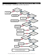
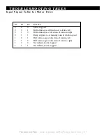
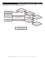
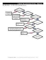
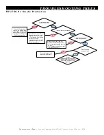
Page 30: ...o Generator Fill D 3 No Steam Production D 4 ES ESi Units No Heat in Convection Mode D 5 No Convection Motor Operation D 6 Input Signal Table for Motor Drive D 7 E 3 E 4 Fan Motor Error D 8 E 53 D 54 Fan Motor Temperature Error D 9 E 35 E 55 Venting Errors D 10 ESi Units No Convection Heat Production D 11 No Smoke Production D 12 Return to Main Table of Contents ii Tro u bleshooting Trees ...

Page 31: ...ltage across terminals 418 and 318 at the X 11 132 and X 11 130 terminal block No Is there voltage across the L 1 and N terminals of the power supply boards s Correct wiring issue between the X 11 130 and X 11 132 terminal blocks and the Power Supply Board s Is the On Off board BA 34778 plugged into the display board Repair connection issue Is there 12 VDC across the V and V terminals of the power...

Page 32: ...faulty solenoid No Yes Check for an obstruction or leak between the Y 1 solenoid and the steam generator Also check for Water supply turned off or disconnected and or plugged filter cartridge Is the generator filling with water It should take approximately 45 seconds to satisfy the B 2 sensing probe No Yes Yes No Yes Yes No No Investigate for scale build up inside tank around water level probes an...

Page 33: ...ent contactor s engaging pulling in No Yes Is there voltage across L 1 L 2 L 3 on K 1 2 3 Correct wiring issue between L 1 2 3 terminals on K 1 2 3 contactor s and T 1 2 terminals on K 41 and T 3 terminal on K 42 NOTE K 41 42 contactors supplied L 1 2 3 from main power terminal block Replace faulty K 1 2 3 contactor s Is there line voltage across T 1 2 3 terminals on K 1 2 3 contactor s No Yes Yes...

Page 34: ...from the HRB High Voltage Relay Board A 2 is L 2 supplied from the N 7 high limit Reset N 7 if tripped Are the convection element contactors K 41 42 being energized Are the K 41 42 contactors pulling in Replace faulty contactor s Investigate wiring issue between main power terminal block and K 41 K 42 Is there line voltage at T 1 T 2 K 41 and T 3 K 42 Investigate wiring issue between K 41 K 42 and...

Page 35: ...motor drive Test for a blown 15A fuse or a wiring issue between the main power terminal block and the 15A fuse block NOTE If fuse is blown the light on the fuse holder should be illuminated Replace faulty contactor Replace faulty motor drive NOTE Ensure jumper position of replacement drive matches existing drive Jumper position ON 208V Jumper position OFF 115V Is the motor drive LED light on Is th...

Page 36: ...Motor stopped 0 0 1 Full rotation speed direction of rotation left 0 1 0 Full rotation speed direction of rotation right 0 1 1 Ramp stopped i e remaining current rotation speed 1 0 1 Half rotation speed direction of rotation left 1 1 0 Half rotation speed direction of rotation right 1 0 0 Not defined motor stopped 1 1 1 Not defined motor stopped I n p ut S i gna l Table for Motor Drive ...

Page 37: ...d Test HES connection points and ensure HES wires are installed on the appropriate terminals of the low voltage relay board Is there 10 VDC across the Red Brown HES wires when the motor is stopped Is there 3 5 VDC across the Red Brown HES wires when the motor is running Replace faulty motor due to failed HES If E3 continues to display contact Alto Shaam factory Technical Support No Yes No Yes Yes ...

Page 38: ...tor high limit switch MHL measured at the X 02 terminal of the low voltage relay board If voltage is present switch is open If motor is hot wait for motor to cool down and retest No Yes Are the MHL wire installed at the appropriate places on the X 02 low voltage relay board Correct wiring issue and retest If motor is hot wait for motor to cool down and retest Is motor cool and switch open Replace ...

Page 39: ... the X 05 connector at pin 3 Power control off and then back on After control screen loads the browning vent motor should be energized and the motor should make one full rotation to the closed vent position If the RBL does not output 12 VDC at this time replace RBL Is there 12 VDC at the browning vent motor No No No Yes Yes Yes Does the valve stop in the closed position Is there 5 VDC across pins ...

Page 40: ...42 Replace faulty contactor s Is there line voltage across L 1 L 2 K 41 and L 3 K 42 No Yes Yes No No Yes No Yes No Yes No Investigate wiring issue between K 41 42 and convection element terminals Is there voltage across all convection element loops Yes No Replace faulty convection element Are the convection elements drawing current Yes No Determine which side of the solenoid coil voltage is missi...

Page 41: ...nt s Are the elements drawing current Determine which side of the coil voltage is missing and correct Terminal 14 on the relay is L 1 switched in from the high voltage relay board Terminal 13 is L 2 constantly supplied from the X 11 130 Blue terminal block No Yes No Yes Is the smoke relay energized Is there line voltage across the smoking elements No Yes The oven should begin producing smoke If th...

Page 42: ...y E 16 Wash Nozzles E 17 Hinge Assemblies E 18 Touch Control E 19 Routing of Ribbon Cable Tabletop E 22 Routing of Ribbon Cable Floor Standing E 23 Combitherm Motor E 24 ES Directional Panel Assemblies E 25 ESi Directional Panel Assemblies E 26 Right hand door assembly dual latch E 27 Recessed door assembly door track dual latch E 29 Left hand door assembly dual latch E 36 Electrical Assembly Tabl...

Page 43: ...30 52 10 17 52 50 39 40 40 21 26 25 26 14 14 14 14 35 10 28 24 29 3 27 10 14 44 7 6 20 56 54 11 9 12 55 57 31 9 12 7 11 26 48 36 26 37 14 38 15 1 33 26 34 43 56 54 10 10 12 33 59 5 2 41 46 58 19 19 30 22 49 52 53 30 23 17 26 10 13 18 25 26 21 35 14 39 54 56 45 26 5 14 44 56 54 22 27 24 28 18 Sprayer Holder Assembly Left Side View Rear View Rear View Wash Pump ...

Page 44: ...29037 Clamp hose 32mm 7 44 SC 22779 Screw pan head phillips M5 1 13 CM 29039 Clamp hose 55mm 2 45 SC 22926 Screw M5 no markings 3 14 CM 29301 Clamp hose 23mm 10 46 SC 25128 Screw truss head M6 4 15 CV 23896 Bracket injector tube 1 47 SL 3836 Sleeve grommet edging 1 16 EB 22221 Elbow steam bypass 1 48 TE 24257 Tee copper 1 3 4 Od 1 17 EB 27207 Elbow 1 7 8 1 49 TE 27204 Tee shower hose 1 18 FT 27406...

Page 45: ...ide Service Parts 20 20ES A 46 51 40 19 17 13 43 53 41 27 7 12 16 21 25 25 29 28 20 27 37 14 38 7 34 60 35 55 44 57 6 30 25 45 57 55 5 32 58 56 28 28 49 28 28 29 11 16 52 10 20 25 12 27 24 27 18 49 18 27 22 27 23 22 28 53 31 47 50 31 47 54 14 6 10 7 13 14 14 36 11 15 8 39 43 27 13 19 1 38 14 37 Left Side View Rear View Plumping Detail A ...

Page 46: ...hose 23mm 9 45 SC 22779 Screw M5 pan head phillips 2 15 CV 23896 Bracket injection tube 2 46 SC 22926 Screw M5 x 16 no markings 3 16 EB 22221 Elbow steam bypass 1 47 SC 25128 Screw truss head M6 4 17 EB 23949 Elbow 1 1 2 90 deg Copper 1 48 SL 3836 Sleeve grommet edging 1 18 EB 27207 Elbow 1 7 8 3 49 TE 24257 Tee 1 3 4 od copper 2 19 FT 27406 Coupling w o stop 1 5 1 50 TE 27204 Tee shower connectio...

Page 47: ...denser tank spacer 8 2 5008873 Condenser tank welding 1 3 CP 28016 Cap 3 4 npt 1 4 PB 26512 Measure probe 1 5 PR 33751 Thermocouple 3050mm wire length 2 6 SA 22212 O ring red seal 1 7 SA 25061 T couple probe seal 2 8 SC 22779 Screw M5 pan head phillips 4 9 WS 22207 Seal measure probe 1 10 WS 22295 Washer flat M5 s s 4 11 WS 22301 Washer M5 split lock 4 12 CP 29358 Cap recessed only 1 13 CM 28145 C...

Page 48: ... a l E 7 parts information 12 5 4 7 12 16 15 9 13 23 22 23 13 8 2 17 14 18 11 3 19 13 1 12 12 12 20 23 22 23 22 6 7 S team Generator Assembly 5011646 6 10es 19 23 22 13 23 22 3 1 20 6 8 7 4 5 12 2 12 12 16 12 9 13 23 22 12 15 14 17 10 13 23 22 17 18 13 23 22 24 24 11 7 5009560 7 14es 10 10es ...

Page 49: ...on spike clip 16 PR 34902 Water level probe 1 4 CM 29038 Clamp hose 38mm 1 17 SA 23932 O ring seal steam element 3 5 CM 29039 Clamp hose 55mm 1 18 SA 25061 T couple probe 1 6 CP 28016 Cap 3 4 npt 1 19 SC 22284 Screw M6 hex head 2 7 DA 24973 Pump steam generator elbow 1 20 ST 22258 Insulation spike 12 8 EB 25106 Steam generator drain 1 21 TU 22256 Tubing wire sleeve varies 9 EL 33411 Heater immersi...

Page 50: ...ion ES i ESi N Rear Left Side Servi ce P arts 1 5 12 38 64 29 57 54 20 51 35 4 14 11 22 25 25 16 16 34 33 21 17 9 6 26 49 26 27 3 12 8 11 9 8 25 47 62 19 26 37 16 36 8 26 14 53 8 11 26 6 49 27 26 16 24 45 16 25 27 9 41 2 31 62 3 28 7 16 58 61 30 33 57 60 44 32 18 8 36 25 52 39 57 46 14 15 22 20 27 21 8 55 54 64 65 ...

Page 51: ...head M6 4 15 FT 27406 Coupling w o stop 1 5 1 48 SL 3836 Sleeve grommet edging 1 16 FT 28124 Clamp hose 24mm 9 49 TE 24257 Tee 1 3 4 Od copper 1 17 FT 29124 Fitting 1 2 barb to 3 8 npt adaptor 1 50 TE 27204 Tee valve sprayer 1 18 FT 29273 Fitting low pressure esi 1 51 VA 25549 Valve 3 8 flow control 0 13 Gpm 1 19 HO 22116 Fitting elbow 90 deg with barb 1 52 VA 26838 Vent motor with switch 1 20 HO ...

Page 52: ... 44 58 6 31 61 58 27 27 49 28 52 15 28 11 8 27 15 53 11 23 26 15 49 15 2 5 34 52 22 52 21 27 54 30 47 55 17 28 8 11 18 35 26 4 50 18 9 21 34 9 17 8 11 42 56 33 57 44 58 3 29 24 25 17 45 60 57 6 31 61 58 27 28 42 56 59 4 49 11 27 8 27 8 27 8 27 49 8 23 26 15 49 15 34 5 12 52 22 52 21 27 54 30 47 56 17 28 8 11 18 26 4 50 18 9 34 9 17 43 38 8 11 59 42 56 1 26 16 21 21 34 ...

Page 53: ...1 1 2 90 deg copper 1 47 SC 25128 Screw truss head M6 4 15 EB 27207 Elbow 1 7 8 4 48 SL 3836 Sleeve grommet edging 1 7ft 16 FT 27406 Coupling w o stop 1 5 1 49 TE 24257 Tee 1 3 4 od copper 2 17 FT 28124 Clamp hose 24mm 10 50 TE 27204 Tee valve sprayer 1 18 FT 29124 Fitting 1 2 barb to 3 8 npt adaptor 3 51 VA 26838 Vent motor with switch 1 19 FT 29273 Fitting low pressure 1 52 VA 27837 Valve 3 8 fl...

Page 54: ... Qty 1 1005540 Condensor Tank Spacer 8 2 5011695 Condensor Tank Welding 6 10esi 7 14esi 10 10esi 10 18esi 1 5009464 Condensor Tank Welding 12 20esi 20 20esi 1 3 CP 28016 Cap 3 4 NPT 1 4 PB 26512 Measure Probe 1 5 PR 33751 Thermocouple 3050 mm Wire Length 2 6 SA 22212 O Ring Red Silicone 1 7 SA 25061 T Couple Probe seal 2 8 SC 22779 Screw Pan Head 4 9 WS 22207 Seal 1 10 WS 22295 Washer Flat 4 11 WS...

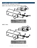
Page 55: ... 1 90 3 2 1 90 5005010 6 10esi 6 10esiN 7 14esi 10 10esi 10 10esiN 10 18esi 12 20esi 5005010 20 20esi Item Part Description Qty 1 5005009 Pressure Box 1 2 EB 25551 Elbow Nylon 1 2 x 3 8 1 3 VA 25549 Valve 3 8 Flow Control 0 12 GPM 1 Item Part Description Qty 1 5008633 Pressure Box 1 2 EB 25551 Elbow Nylon 1 2 x 3 8 1 3 VA 27837 Valve 3 8 Flow Control 0 35 GPM 1 ...

Page 56: ...12 Side rack left hand 10 10esiN CC 1 5005648 Water injection tube 10 18 12 20 20 20 1 1009936 Side rack left hand 10 18es 10 18esi CC 1 10 5009271 Side rack right hand 6 10es 6 10esi CC 1 3 GS 26639 Door gasket 6 10es 6 10esi 7 14es 7 14esi 1 5013794 Side rack right hand 6 10es 6 10esi CC 05 11 1 GS 36638 Door gasket 10 10es 10 10esi 10 18es 10 18esi 1 5009087 Side rack right hand 6 10esiN CC 1 G...

Page 57: ... Oven Light Item Part Description Qty 1 PB 26960 Hand Shower Holder 1 2 WS 22295 Flat Washer 4 3 WS 22301 Locking Washer 4 4 SC 22766 Philips Screw 4 5 HO 26964 Hand Shower Hose 6 10 7 14 10 20 12 18 1 HO 26965 Hand Shower Hose 20 20 1 6 WS 29074 Hand Shower Hose Washer 1 7 5011315 Hand Shower Sprayer 1 S moker chip tray Assembly 3 3 2 1 Item Part Description Qty 1 1010343 Smoker Box Holder 1 2 50...

Page 58: ...le Item Part C Description Qty 1 5005474 Water Injection Tube 6 10es 6 10esi 10 10es 10 10esi 1 5009646 Water Injection Tube 7 14es 7 14esi 6 10esiN 10 10esiN 1 5005648 Water Injection Tube 10 18es 10 18esi 12 20es 12 20esi 20 20es 20 20esi 1 2 1001204 Disintegration Box 1 3 SC 23737 Screw M5 Hex Head for Disintegration Box 1 1 NOT SHOWN ...

Page 59: ...nge R H 1 9 HG 28155 Lower Hinge L H 1 10 SC 22284 Hex Head Screw M6 x 16 1 11 HG 25101 Lower Hinge Ratchet 1 12 WS 22323 Washer 1 13 HG 26299 Lower Hinge 1 Bo t t o m Hinge Assembly 5 4 3 1 2 8 6 7 5 13 12 10 11 5 4 9 Item Part Description Qty 1 HG 28094 Hinge Ratchet Part 2 1 2 SC 28891 Screw Truss Head 3 3 SC 25102 Screw 1 4 PG 25132 Plug 1 5 WS 2294 Washer Lock 1 6 WS 22094 Washer Flat 1 7 WS ...

Page 60: ...34918 Fan Cooling 115V 1 FA 34919 Fan Cooling 230V 1 not shown 4 14 6 2 14 5 14 1 7 17 16 13 19 18 3 8 9 10 15 DETAIL B BROWN WIRE POSITIVE WHITE WIRE NEGATIVE RED TAB 8 8 7 COVER HIDDEN TO SHOW SPEAKER 5010483 11 12 Item Part Control Panel Description 5010483 Qty 12 BA 34922 Compact Flash 1 13 GS 23622 Gasket Adhesive 4 5 1 14 NU 25095 Nut Knurled M3 6 15 NU 27851 Nut Hex 5mm with Star Washer 4 1...

Page 61: ...A 34919 Fan Cooling 230V see arrow for 3 1 5 GL 29267 Cover Relay Board 1 6 SC 22271 Screw Philips Head M4 2 7 SC 22753 Screw Round Hanging Rack 2 8 SC 22766 Screw Pan Head Philips 1 9 SC 29261 Screw M4x50mm 4 10 SC 29276 Screw M4x30mm 2 11 WS 22294 Washer Flat M4 6 12 WS 22295 Washer Flat M5 1 13 WS 22300 Washer Split Lock M4 6 14 WS 22301 Washer Split Lock M5 1 6 2 10 9 13 11 13 11 1 14 3 5 7 50...

Page 62: ...THE TOP OF THE FRAME S SIDE FLANGE 1 7 5 5 7 STEP ONE 4 3 CONNECT CABLES STEP THREE USE FIXTURE 67180 AS SHOWN TO LOCATE THE BOTTOM EDGE OF THE GASKET TAPE TOUCH SCREEN DISPLAY ASSY COMBI 5013093 Item Part Control Panel Preplacement Kit 5013093R Includes Qty 1 1010646 Mounting Bracket Display Board 1 2 BA 34776 Board Bonded Display and Touch Field Kit 1 3 CB 34915 Cable Touch Board 1 4 CB 34916 Ca...

Page 63: ... inf o r ma tion Co m m o n Pa r t s Co m b i t h e r m El e c t r i c Te c h n i c a l Se r v i c e Ma n u a l E 22 Ri bb on cable routing 6 10es esi 7 14es esi 6 10esiN 10 10es esi Ribbon Cable Power Cable ...

Page 64: ...m m o n Pa r t s Co m b i t h e r m El e c t r i c Te c h n i c a l Se r v i c e Ma n u a l E 23 parts information 12 20es esi Ri bb on cable routing 20 20es esi 10 10esiN 10 18es Ribbon Cable Power Cable ...

Page 65: ...OPPER PASTE IN THIS LOCATION 11 3 8 9 14 5 4 1 10 12 13 2 16 6 15 NOTE 1 ASSEMBLY SEQUENCE MOUNT THE FOLLOWING ITEMS TO THE MOTOR SHAFT IN THIS ORDER PLACE MOTOR BAFFLE OVER SHAFT MOUNT BRASS MOTOR SLEEVE USING MALLET PIPE COAT BOTTOM PART OF SHAFT WITH COPPER PASTE PLACE SPRING THEN MOTOR SHAFT BUSHING THEN SEALING WASHER AND FINALLY PLACE KEY IN KEYWAY OF SHAFT 5011958 Item Part Description Qty ...

Page 66: ... Panel 7 14es 1 1009997 Directional Panel 10 10es 1 1009924 Directional Panel 10 18es 1 1010164 Directional Panel 12 20es 1 1010094 Directional Panel 20 20es 1 2 1006601 16 GA Directional Panel Spacer 2 3 WS 24090 Holding Lock Clip 2 4 CL 24089 Clip Lock W 3 Washers 2 5 SC 22753 Screw SS Round Hanging Rack 2 6 NU 22770 Nut Threaded Insert M6 2 6 10es 7 14es 10 10es 10 18es 12 20es 5009329 effectiv...

Page 67: ...si 1 1009997 Directional Panel 10 10esi 1 1009828 Directional Panel 10 10esiN 1 1009924 Directional Panel 10 18esi 1 1010164 Directional Panel 12 20esi 1 1010094 Directional Panel 20 20esi 1 2 1006601 16 GA Directional Panel Spacer 2 3 WS 24090 Holding Lock Clip 2 4 CL 24089 Clip Lock W 3 Washers 2 5 SC 22753 Screw SS Round Hanging Rack 2 6 NU 22770 Nut Threaded Insert M6 2 6 10esi 6 10esiN 7 14es...

Page 68: ...asher M4 split lock 2 2 SC 22282 Screw phillips oval 2 19 SC 22271 Screws M4 phil 2 3 HG 25079 Hinge upper ratchet 1 20 LT 29086 Inner door latch 2 4 HG 25078 Hinge anchor 2 21 1011417 Spacer inner door latch 2 5 PI 26974 Pin lower 1 22 BM 27116 Bumper silicon for glass door 2 6 PI 26973 Pin upper 1 23 GS 26639 Door Gasket 6 10es 6 10esi 7 14es 7 14esi 1 7 HG 25077 Hinge top stop 1 GS 36638 Door G...

Page 69: ...chet 1 4 HG 25078 Hinge anchor 2 21 SC 22282 Screw phillip oval 1 5 SC 25085 Screw M6 oval head 1 22 1010294 Sweep gasket holder 1 6 HG 25077 Hinge top stop 1 23 WS 22295 Washer Flat M5 4 7 BM 27146 Bumper stop inner door 2 24 WS 22301 Washer M5 split lock 4 8 HD 26966 Handle door right 1 25 SC 27109 Screw M5 truss head 4 9 BM 27116 Bumper silicon for glass door 4 26 1010070 Backer support sweep g...

Page 70: ...k 2 2 PI 26973 Pin upper 1 18 SC 22271 Screws M4 phil 2 3 HG 25078 Hinge anchor 4 19 WS 22294 Washer flat M4 2 4 RI 27108 Rivet sealed 19 20 WS 22302 Washer M6 split lock 2 5 SC 22282 Screw phillips oval 2 21 SC 25125 Screw truss head M6 2 6 HG 25077 Hinge top stop 1 22 PG 24789 Plug 15mm 2 7 SC 25128 Screw truss head M6 2 23 PI 26974 Pin lower 1 8 HD 26966 Handle door right 1 24 GS 26639 Door Gas...

Page 71: ...1 5009030 Trolley Assembly Recessed Door 10 10es 10 10esiN 10 18es 1 3 HG 25101 Hinge Lower Ratchet 1 4 HG 28040 Hinge Recessed Door Lower 1 5 HG 28041 Hinge Recessed Door Upper 1 6 PG 25460 Hole Plug 13 32 Diameter 1 7 SC 22279 Screw Hex Head M8 2 8 SC 22284 Screw Hex Head M6 1 9 SC 25102 Screw Axis Upper Hinge 1 10 WS 22298 Washer M8 3 11 WS 25124 Eccentric Washer 1 12 WS 25127 Covering Washer f...

Page 72: ...g includes Bearing Retainer 2 3a Bearing Retainer 2 4 BK 28042 Block Guide Long 1 5 BK 28043 Block Guide Short 2 6 BK 28084 Block Stop Recessed Door 2 7 HG 28102 Hinge Ratchet Recessed Door 2 8 NU 22292 Nut Hex M8 7 9 SC 24388 Screw SHC M8 4 10 SC 24390 Screw SHC M6 6 11 SC 26060 Screw Hex Head M5 2 12 SC 28082 Screw Hex Head M10 2 13 SC 28088 Bolt Carriage M8 3 14 SC 28421 Screw Hex Head M6 4 15 ...

Page 73: ...ew 4 4 HG 25078 Hinge anchor 4 24 1011417 Spacer latch inner door 2 5 SC 22284 Screw M6 hex head 6 25 SC 22271 Screws M4 phillips 2 6 SC 25085 Screw M6 oval head 1 26 WS 22300 Washer M4 split lock 2 7 HG 25077 Hinge top stop 1 27 WS 22294 Washer flat M4 2 8 BM 25072 Bumper rubber 2 28 SC 25091 Screw M5 sltd set screw flat 12 9 LT 34777 Latch inner door 2 29 SP 27657 Spacer glass 20mm 7 10 RI 27108...

Page 74: ...r 20 20es 20 20esi 8 BK 27412 Block Recessed Door 12 20es 12 20esi 4 6 SC 22283 Screw Phillips Oval Head M6 8 7 RA 28396 Rail Bottom 1 8 PG 24384 Plug Screw 7 9 SC 24388 Screw SHC M8 7 10 WS 24396 Washer Serrated Bevel M8 7 11 SP 28440 Rail Spacer 7 12 1011706 Plate Hinge Mounting Door 1 13 SC 29403 Screw Truss Head M8 4 14 SC 22926 Screw Hex Head M8 2 15 WS 22301 Washer Split Lock M5 2 16 WS 2229...

Page 75: ... 20es 20 20esi 1 5010432 Recessed Door Assembly 12 20es 12 20esi 1 5 HG 25101 Hinge Lower Ratchet 1 6 HG 28041 Hinge Recessed Door Upper 1 7 HG 28411 Hinge Recessed Door Lower 1 8 PG 25460 Hole Plug 13 32 Diameter 2 9 SC 22279 Screw Hex Head M8 1 10 SC 22284 Screw Hex Head M6 1 11 SC 25102 Upper Hinge Axis Screw 1 12 SC 26060 Screw Hex Head M5 4 13 WS 22295 Washer Flat M5 4 14 WS 22298 Washer M8 3...

Page 76: ... BG 28037 Bearing 2 4 BK 28042 Block Guide Long 1 5 BK 28043 Block Guide Short 2 6 BK 28084 Block Stop Recessed Door 4 7 HG 28102 Hinge Ratchet Recessed Door 2 8 NU 22292 Nut Hex M8 7 9 SC 24388 Screw SHC M8 4 10 SC 24390 Screw SHC M6 12 11 SC 28082 Screw Hex Head M10 2 12 SC 28088 Bolt Carriage M8 3 13 SC 28421 Screw Hex Head M6 4 14 WS 24396 Washer Serrated Bevel M8 4 15 WS 28083 Washer Serrated...

Page 77: ... SP 27212 Spacer window latch 1 19 SC 22271 Screws M4 phil 2 6 1009381 Door spacer 14 ga 1 20 WS 22300 Washer M4 split lock 2 7 SC 22282 Screw phillps oval 2 21 WS 22294 Washer flat M4 2 8 HG 25077 Hinge top stop 1 22 HD 26967 Handle door left 1 9 HG 25078 Hinge anchor 2 23 BM 27116 Bumper 2 10 PI 26973 Pin upper 1 24 GS 26639 Door Gasket 6 10es 6 10esi 7 14es 7 14esi 1 11 BM 25072 Bumper rubber 5...

Page 78: ...er Supply Assembly Dual 1 7 TM 34305 Terminal Screwless End 3 8 CN 34913 Contactor 230V 1 9 CN 3654 Contactor 40 Amp 2 10 FU 34772 Fuse 15 Amp 2 11 FU 34770 Fuse Holder 3 Bank 1 12 TM 34315 Terminal End Plate 1 13 FU 33184 Fuse Slo Blo 2 Amp 4 Item Part Description Qty 14 FU 33452 Neozed 6 3 Amp 4 15 TM 34311 Terminal Fuse Holder 8mm 4 16 TM 34307 Terminal Spring Orange 6mm 4 17 TM 34308 Terminal ...

Page 79: ...le Motor 2 22 WS 22294 Washer Flat M4 4 23 WS 22300 Washer Split Lock M4 4 24 SC 29261 Screw M4x50mm 4 25 5012022 Din Rail Assembly 20 20es 208 240V 1 24 21 2 3 5 23 22 20 19 5 18 5 5 5 6 5 6 5 5 5 10 16 12 9 5 15 14 1 8 7 13 4 4 17 11 25 5011965 19 20 2 4 4 4 1 3 3 3 DIN RAIL ASSY SCREW TM LONG 5011999 Item Part Description 5011999 Qty 1 TM 33064 Jumper Bar 3 Pole 33mm SQ 3 2 TM 34305 Terminal Sc...

Page 80: ... 10esiN 10 10esiN A C B 9 4 5 7 8 6 3 2 1 45 36 37 30 31 36 29 28 34 26 27 32 28 35 33 31 3 2 D 10 17 4 12 13 14 11 15 16 E 23 24 25 18 18 21 22 19 20 Detail D Detail B Detail A Bottom View Detail C 70 48 46 47 49 45 55 54 33 56 32 17 12 13 14 11 15 66 64 67 64 68 64 64 67 64 66 65 64 61 63 62 14 60 58 59 23 69 41 39 38 44 4 43 42 40 3 2 53 51 52 50 ...

Page 81: ...0 29 BU 3009 Bushing snap 5 16 1 30 5010555 Left side restr assembly 1 31 SC 22779 Screw phillips pan head M5 8 32 PL 28413 Pull key ring 3 4 manual 2 33 CL 28849 Clip crimp for 1 16 wire cable 2 34 SC 27325 Screw M6 2 35 TU 33178 Conduit flex liquid tight 24 1 Item Part Description Qty 36 CR 33179 Connector flex nylon sweep 2 37 1007539 Level probe cover w hood 1 38 PG 25460 Plug hole 13 32 Dia 1...

Page 82: ... 10esi 7 14es 7 14esi 10 10es 10 10esi 10 18es 10 18esi A C B 4 5 8 9 7 3 2 D 6 13 10 13 54 38 39 32 30 38 33 31 35 23 22 15 37 36 34 30 3 2 29 28 27 26 43 31 25 24 E 21 16 16 12 17 14 18 19 20 15 1 6 41 43 44 46 4 45 42 40 47 3 2 54 51 53 52 13 50 48 49 7 9 56 55 34 57 15 70 63 55 65 62 67 61 68 69 67 60 15 57 Detail D Detail B Detail A Bottom View Detail C ...

Page 83: ... lock M6 4 29 SC 22284 Screw hex head M6 4 30 SC 22779 Screw pan head phillips M5 8 31 NU 22289 Nut hex M5 10 32 5011186 Left side restr Assembly 1 33 BU 3009 Bushing snap 5 16 1 34 CL 28849 Clip crimp for 1 16 wire cable 2 35 SC 27325 Screw M6 2 Item Part Description Qty 36 NP 27538 Valve holder assembly 1 37 TU 33178 Conduit flex liquid tight 30 1 38 CR 33179 Connector flex nylon sweep 2 39 1007...

Page 84: ...ing 2 10 SP 33832 Spacer lock mount panel 4 11 5010631 Control panel weld 1 12 BA 34476 Board control VHes CombiHood 1 13 CR 33717 Connector 10 pin 1 14 RL 33930 Relay power spdt 15a 12v Dc 1 15 CR 3849 Connector dual spade 1 4 1 16 BU 25094 Bushing brass distance 2 Item Part Description Qty 17 WS 22299 Washer split lock M3 2 18 SC 22270 Screw phillips head M3 2 19 BA 34508 40 Watt power supply 12...

Page 85: ...25 6 10esi 6 10esiN 7 14esi 10 10esi 10 10esiN F 13 77346 10 18es F 16 77364 10 18esi F 20 77366 12 20es F 23 77347 12 20esi F 27 77336 20 20es F 30 77339 20 20esi F 35 380 415V 50Hz 3Ph 77386 6 10es F 40 77329 6 10esi 6 10esiN 7 14esi 10 10esi F 44 77330 7 14es 10 10es F 47 77348 10 18es F 51 77349 10 18esi F 56 77373 12 20es F 60 77374 12 20esi F 65 77340 20 20es F 69 77342 20 20esi F 74 440 480...

Page 86: ......

Page 87: ......

Page 88: ......

Page 89: ......

Page 90: ......

Page 91: ......

Page 92: ......

Page 93: ......

Page 94: ......

Page 95: ......

Page 96: ......

Page 97: ......

Page 98: ......

Page 99: ......

Page 100: ......

Page 101: ......

Page 102: ......

Page 103: ......

Page 104: ......

Page 105: ......

Page 106: ......

Page 107: ......

Page 108: ......

Page 109: ......

Page 110: ......

Page 111: ......

Page 112: ......

Page 113: ......

Page 114: ......

Page 115: ......

Page 116: ......

Page 117: ......

Page 118: ......

Page 119: ......

Page 120: ......

Page 121: ......

Page 122: ......

Page 123: ......

Page 124: ......

Page 125: ......

Page 126: ......

Page 127: ......

Page 128: ......

Page 129: ......

Page 130: ......

Page 131: ......

Page 132: ......

Page 133: ......

Page 134: ......

Page 135: ......

Page 136: ......

Page 137: ......

Page 138: ......

Page 139: ......

Page 140: ......

Page 141: ......

Page 142: ......

Page 143: ......

Page 144: ......

Page 145: ......

Page 146: ......

Page 147: ......

Page 148: ......

Page 149: ......

Page 150: ......

Page 151: ......

Page 152: ......

Page 153: ......

Page 154: ......

Page 155: ......

Page 156: ......

Page 157: ......

Page 158: ......

Page 159: ......

Page 160: ......

Page 161: ......

Page 162: ......

Page 163: ......

Page 164: ......

Page 165: ......

Page 166: ......

Page 167: ......

Page 168: ......

Page 169: ......

Page 170: ......

Page 171: ......

Page 172: ......

Page 173: ......

Page 174: ......

Page 175: ......

Page 176: ......

Page 177: ......

Page 178: ......

Page 179: ......

Page 180: ......

Page 181: ......

Page 182: ......

Page 183: ......

Page 184: ......

Page 185: ......

Page 186: ......

Page 187: ......

Page 188: ......

Page 189: ......

Page 190: ......

Page 191: ......

Page 192: ......

Page 193: ......

Page 194: ...W a t e r S t r e e t l P O B o x 4 5 0 l M e n o m o n e e F a l l s W i s c o n s i n 5 3 0 5 2 0 4 5 0 l U S A phone 262 251 3800 800 558 8744 u s a canada l fax 262 251 7067 800 329 8744 u s a l www alto shaam com printed in u s a ...

Reviews: