background image

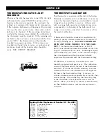
# 8 2 8   O p e r a t i o n   a n d   C a r e   M a n u a l   •   13.

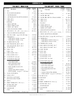
S E R V I C E

8 / 2 7 / 0 2

Quantity

A/S Part

Description

per Unit

Number

1. TOP

1

11559

2. TOP MOUNTING SCREWS

2

SC-2425

3. CASTER BRACKET

2

4974

4. CASTER BRACKET MOUNTING SCREWS

8

SC-2425

5. CORD, 125V

1

CD-33367

CORD, 230V

1

CD-3922

BUSHING

1

BU-3011

6. CASING, BOTTOM

1

14523

CASING, RIGHT-HAND

1

14332

CASING, LEFT-HAND

1

14333

7. CASING MOUNTING SCREWS

6

SC-2425

8. INSULATION:  25” x 120” 

(635mm x 3048mm)

1

IN-22364

9. CABLE CONNECTION HARDWARE

10. HEATING CABLE:  Length 144’ (43891mm)

1

CB-3045

11. THERMOSTAT

1

TT-3057

— THERMOSTAT KNOB, Fahrenheit

1

KN-3469

— THERMOSTAT KNOB, Celsius

1

KN-3474

12. TEMPERATURE GAUGE

1

GU-3273

13. HEAT INDICATOR LIGHT, 125V

1

LI-3493

HEAT INDICATOR LIGHT, 230V

1

LI-3923

14. LIGHT SWITCH

1

SW-3887

15. BULB, 125V

2

LP-3480

BULB, 230V

2

LP-3606

16. BULB SOCKET, 125V

2

RP-3952

BULB SOCKET, 230V

2

RP-3955

17. GLASS DOOR, Left-hand

1

4972

18. GLASS DOOR, Right-hand

1

4973

EACH DOOR INCLUDES:

— TOP DOOR HINGE

1

HG-2892

— BOTTOM DOOR HINGE

1

HG-23952

— TOP HINGE PIVOT PIN

1

PI-2894

— BOTTOM HINGE PIVOT PIN

1

PI-23953

— HANDLE

1

HD-2910

— HANDLE MOUNTING SCREWS

2

SC-2911

— DOOR GASKET:  Length 6.3’ (1920mm) 1

GS-2891

19. GLASS, BACK (REAR)

1

4971

20. DOOR LATCH 

2

LT-23187

21. SIDE RACK, LEFT-HAND

1

SR-2849

SIDE RACK, RIGHT-HAND

1

SR-2850

22. SHELF

3

SH-2851

23. BIMET THERMOSTAT, 230V 

ONLY

1

TT-3859

24. FILTER (LINE), 230V

1

FI-33225

FILTER BRACKET

1

13001

25. FUSEHOLDER

1

FU-3884

FUSE

1

FU-3883

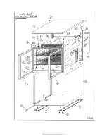
SERVICE VIEW • following pages

8 / 2 7 / 0 2

Quantity

A/S Part

Description

per Unit

Number

1. TOP

1

11559

2. TOP MOUNTING SCREWS

2

SC-2425

3. CASTER BRACKET

2

4974

4. CASTER BRACKET MOUNTING SCREWS

8

SC-2425

5. CORD, 125V

1

CD-33367

CORD, 230V

1

CD-3922

BUSHING

1

BU-3011

6. CASING, BOTTOM

1

14523

CASING, RIGHT HAND

1

14332

CASING, LEFT HAND

1

14333

7. CASING MOUNTING SCREWS

6

SC-2425

8. INSULATION:  25” x 120” 

(635mm x 3048mm)

1

IN-22364

9. CABLE CONNECTION HARDWARE

10. HEATING CABLE:  Length 144’ (43891mm)

1

CB-3045

11. THERMOSTAT

1

TT-3057

— THERMOSTAT KNOB, Fahrenheit

1

KN-3469

— THERMOSTAT KNOB, Celsius

1

KN-3474

12. TEMPERATURE GAUGE

1

GU-3273

13. HEAT INDICATOR LIGHT, 125V

1

LI-3493

HEAT INDICATOR LIGHT, 230V

1

LI-3923

14. LIGHT SWITCH

1

SW-3887

15. BULB, 125V

2

LP-3480

BULB, 230V

2

LP-3606

16. BULB SOCKET, 125V

2

RP-3952

BULB SOCKET, 230V

2

RP-3955

17. GLASS DOOR, Left-hand

2

4972

18. GLASS DOOR, Right-hand

2

4973

EACH DOOR INCLUDES:

— TOP DOOR HINGE

1

HG-2892

— BOTTOM DOOR HINGE

1

HG-23952

— TOP HINGE PIVOT PIN

1

PI-2894

— BOTTOM HINGE PIVOT PIN

1

PI-23953

— HANDLE

1

HD-2910

— HANDLE MOUNTING SCREWS

2

SC-2911

— DOOR GASKET:  Length 6.3’ (1920mm)

1

GS-2891

19. DOOR LATCH 

4

LT-23187

20. SIDE RACK

2

SR-2213

21. SHELF

3

SH-2114

22. BIMET THERMOSTAT, 230V only

1

TT-3859

23. FILTER (LINE), 230V

1

FI-33225

FILTER BRACKET

1

13001

24. FUSEHOLDER

1

FU-3884

FUSE

1

FU-3883

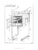
SERVICE VIEW • following pages

750-GDU - REACH-IN

750-GDU/PT - PASS-THRU

Summary of Contents for HALO HEAT 750-GDU

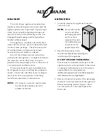
Page 1: ...t P O Box 450 Menomonee Falls Wisconsin 53052 0450 USA PHONE 262 251 3800 800 558 8744 USA CANADA FAX 262 251 7067 800 329 8744 U S A ONLY WEBSITE www alto shaam com P R I N T E D I N U S A H o t F o o d V i s u a l M e r c h a n d i s e r E l e c t r i c Models 750 GDU 750 GDU PT INSTALLATION OPERATION MAINTENANCE ...

Page 2: ...or installing the equipment model Contact the Alto Shaam service depart ment if you have any questions concerning installation operation or maintenance NOTE All claims for warranty must include the full model number and serial number of the unit UNPACKING 1 Carefully remove the appliance from the carton or crate NOTE Do not discard the carton and other packaging material until you have inspected t...

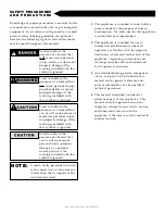
Page 3: ...ard that can or will cause minor personal injury property damage or a potential unsafe practice if the warning included with this symbol is ignored Used to notify personnel of instal lation operation or maintenance information that is important but not hazard related 1 This appliance is intended to cook hold or process foods for the purpose of human consumption No other use for this appliance is a...

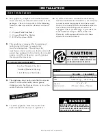
Page 4: ...de to side and back to back with the use of a spirit level 5 In order to maintain standards established by the National Sanitation Foundation all stationary counter mounted equipment must be secured flush to the counter and the entire base sealed to the counter with NSF approved sealant or equipped with 4 102mm legs to provide mini mum unobstructed space beneath the unit Warranty will become null ...

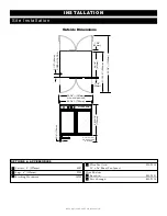
Page 5: ...D LOCATION 28 15 16 735mm WITH DOORS OPEN 52 3 4 1340mm 1 3 8 35mm 3 4 19mm 6 3 4 171mm FOR CASTERS OR LEGS ALTO SHAAM 30 3 4 781mm Outside Dimensions OPTIONS ACCESSORIES Casters 5 127mm 4007 Legs 6 152mm 5205 Stacking Hardware 14209 Wire Pan Grid PN 2115 18 x 26 Sheet Pan Insert Wire Shelves Reach in SH 2851 Pass through SH 2114 ...

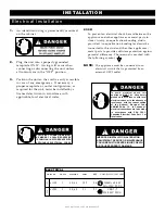
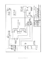
Page 6: ...difference The terminal is marked with the following symbol NOTE The appliance must be connected to an electrical circuit that is protected by an external GFCI outlet 828 Operation and Care Manual 5 INSTALLATION Electrical Installation ELECTRICAL CONNECTIONS MUST BE MADE BY A QUALIFIED SERVICE TECHNICIAN IN ACCORDANCE WITH APPLICABLE ELECTRICAL CODES To avoid electrical shock this appliance MUST b...

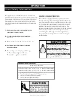
Page 7: ...he unit treat glass with care Remember glass can shatter HEATING CHARACTERISTICS The cabinet is equipped with a special low heat density heating cable Through the Halo Heat con cept the heating cable is mounted against the walls of the warming compartment to provide an evenly applied thermostat controlled heat source The design and operational characteristics of the cabinet eliminate the need for ...

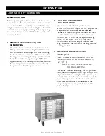
Page 8: ...de the unit reaches the temperature set by the operator 2 LOAD THE CABINET WITH HOT FOOD ONLY The purpose of the holding cabinet is to maintain hot food at proper serving temperature Only hot food should be placed into the cabinet Before loading the cabinet with food use a food thermometer to make certain all products are at an internal temperature range of 140 to 160 F 60 to 71 C Any food product...

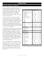
Page 9: ...m of 1 to 2 minutes must be the only time period allowed for the initial heat to be released from the product This unit is equipped with a thermostat control between 60 and 200 F 16 and 93 C If the unit is equipped with vents close the vents for moist holding and open the vents for crisp holding Use a metal stemmed thermometer to measure the internal temperature of the product being held Adjust th...

Page 10: ...ed foods should be removed and the area wiped as soon as possible but at the very least a minimum of once a day Always thoroughly rinse surfaces after using a cleaning agent and wipe standing water as quickly as possible after rinsing CLEANING AGENTS Use non abrasive cleaning products designed for use on stainless steel surfaces Cleaning agents must be chloride free compounds and must not contain ...

Page 11: ... door gaskets thoroughly since these areas harbor food debris 7 Rinse surfaces by wiping with sponge and clean warm water 8 Remove excess water with sponge and wipe dry with a clean cloth or air dry Leave door open until interior is completely dry Replace shelves 9 Interior can be wiped with a sanitizing solution after cleaning and rinsing This solution must be approved for use on stainless steel ...

Page 12: ...e method of measuring safe temperatures of both hot and cold foods is by internal product temperature A quality thermometer is an effective tool for this purpose and should be routinely used on all products that require holding at a specific temperature A comprehensive sanitation program should focus on the training of staff in basic sanitation procedures This includes personal hygiene proper hand...

Page 13: ...acy of the thermostat calibration A thermostat should be checked or recalibrated by placing a quality thermal indicator at the center of an empty holding cavity DO NOT CALIBRATE WITH ANY FOOD PRODUCT IN THE CABI NET The thermostat should be set at 140 F 60 C and should be allowed to stabilize at that set ting for a minimum of one hour Following tempera ture stabilization the center of the thermal ...

Page 14: ...0V ONLY 1 TT 3859 24 FILTER LINE 230V 1 FI 33225 FILTER BRACKET 1 13001 25 FUSEHOLDER 1 FU 3884 FUSE 1 FU 3883 SERVICE VIEW following pages 8 27 02 Quantity A S Part Description per Unit Number 1 TOP 1 11559 2 TOP MOUNTING SCREWS 2 SC 2425 3 CASTER BRACKET 2 4974 4 CASTER BRACKET MOUNTING SCREWS 8 SC 2425 5 CORD 125V 1 CD 33367 CORD 230V 1 CD 3922 BUSHING 1 BU 3011 6 CASING BOTTOM 1 14523 CASING R...

Page 15: ... 828 Operation and Care Manual 14 ...

Page 16: ... 828 Operation and Care Manual 15 ...

Page 17: ... 828 Operation and Care Manual 16 ...

Page 18: ... 828 Operation and Care Manual 17 ...

Page 19: ...from the shipping date whichever occurs first THIS WARRANTY DOES NOT APPLY TO 1 Calibration 2 Replacement of light bulbs and or the replacement of display case glass due to damage of any kind 3 Equipment damage caused by accident shipping improper installation or alteration 4 Equipment used under conditions of abuse misuse carelessness or abnormal conditions including but not limited to equipment ...

Reviews: