#895 Operation & Care Manual •
1.
U N P A C K I N G a n d S E T - U P
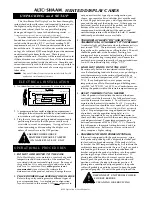
The Alto-Shaam Hot Display Case has been thoroughly
tested, checked for calibration, and inspected to insure only
the highest quality display case is provided. When you
receive your cabinet, check for any possible shipping
damage and report it at once to the delivering carrier.
See
Transportation Damage and Claims section located in this manual.
In order to maintain established National Sanitation
Foundation standards, all stationary floor models must be
sealed to the floor with a R.T.V. or silastic meeting N.S.F.
requirements or have 6"(153mm) unobstructed clearance
beneath the unit. Counter and table units must be mounted
on legs of a sufficient 4"(102mm) height to provide minimum
unobstructed space beneath the unit. These legs are
supplied with the unit. Warranty will become null and void
if these directions are not followed. Save all the information
and instructions packed inside the deli case. Complete and
return the warranty card to the factory as soon as possible to
assure prompt service in the event of a warranty parts and
labor claim.
NOTE
:
Any and all claims for warranty must include the full model
number and serial number of the unit.
E L E C T R I C A L I N S TA L L AT I O N
1
. An identification tag is permanently mounted on case.
2. A proper receptacle or outlet configuration or permanent
wiring for this unit must be installed by a licensed electrician
in accordance with applicable, local electrical codes.
3. Plug the case into a properly grounded receptacle only,
positioning the unit so that the power cord is easily
accessible in case of an emergency. Arcing will occur
when connecting or disconnecting the display case
unless all controls are in the OFF position.
O P E R AT I O N A L P R O C E D U R E S
1.
DO NOT ADD WATER TO THE CASE
Halo Heat display cases maintain a constant but gentle
temperature and eliminate much of the moisture loss
associated with conventional display cases. Because of
this gentle heat, it is not necessary to add water to the
deli case. As a matter of fact,
adding water is not
recommended
since water will accelerate the
deterioration of the product, and may damage the case.
2.
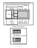
PLACE DIVIDERS and SERVING PANS IN CASE
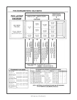
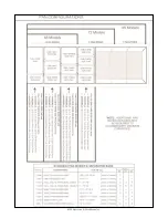
Refer to the pan layout diagrams for different types of
pan accommodations. A complete pan configuration
layout is located in this manual. It is very important to
note, no matter what type of pan configuration you
choose, pan separator bars or divider bars must be used
to close all gaps between pans, and all gaps between the
pans and the edges of the display case. If these gaps are
not closed, most of the heat will be pulled out of the
bottom of the case, into the display area. As a
consequence, heat distribution will be uneven and
uniform temperature will be difficult to hold. If needed,
additional pan divider bars are available.
3.
TURN DISPLAY LIGHTS “ON” AND SET THE
THERMOSTAT(s) AT NUMBER “10” TO PREHEAT
A indicator light will illuminate when the thermostat(s) is
(are) turned “ON.” The indicator(s) will remain lit as
long as the unit is preheating or calling for heat. The unit
should be preheated, at the number 10 setting, for a
minimum of twenty minutes before loading the case with
food. When preheating is completed, or whenever the
unit reaches any temperature set by the operator between
1 and 10, the indicator light(s) will go “OUT”.
4.
LOAD HOT FOODS INTO THE UNIT
Be certain only hot food is transferred into the display
case. Before loading food into the case, use a pocket-type
meat thermometer to make certain all products have
reached an internal temperature of 140° to 160° F. (60° to
71°C). If any food product is not at proper serving
temperature, use a Halo Heat cooking and holding oven,
set at 250° to 275°F (121° to 135°C), or a Combitherm oven
to bring the product within the correct temperature range.
5.
RESET THERMOSTAT AS NEEDED
After all product is loaded into the unit and the doors
are closed, reset the thermostat. For fully enclosed cases,
reset the thermostat to number 8. For self-service units,
maintain the thermostat at number 9 or 10. Cases with a
self-service section should be set at number 9 or 10 for the
self-service section only.
These settings will not necessarily
be final.
Proper temperature range depends on the type
of products and the quantities being held, so it is
necessary to periodically use a pocket thermometer to
check each item to make certain the correct temperatures
are being maintained. Proper temperature range is
between a minimum of 140-160°F (60°-71°C). Normally
this will require a thermostat setting between 6 and 8 in
fully enclosed cases. Self-service cases or sections will
always require a higher setting.
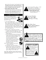
6.
PLACEMENT OF FOOD PROBE (OPTIONAL)
If the unit is equipped with the probe accessory, wipe
each probe and probe tip with a disposable alcohol pad
to clean and sanitize before using. If the probe is left in
its bracket, the LED temperature display will indicate the
ambient air temperature inside the case. To place a probe
into food kept in the case, remove the probe from the
bracket and push the probe tip halfway into the product,
positioning the tip at the center of the food mass. If
placing into solid foods such as meat roast or poultry
breasts, push the probe in from a straight downward
position or in from the side to the center position. If
placing into a semi-liquid or liquid product, the probe
cable will probably need to be secured to keep the probe
positioned properly. Do not let the probe tip touch the
DISCONNECT UNIT FROM POWER
SOURCE BEFORE
CLEANING OR SERVICING
HEATED DISPLAY CASES
®
EXAMPLE
S E R I A L N U M B E R A N D WA R R A N T Y C O D E
M A X I M U M R AT E D
WAT TA G E
I D E N T I F I C AT I O N M O D E L N U M B E R
M A X I M U M R AT E D V O LTA G E
M A X I M U M R AT E D F R E Q U E N C Y
MODEL
SERIAL NO.
WATTS
1 PH
VOLTS
xxx-xx
xxxx-xx
xxxx
xx
HZ
xxx
AC
ALTO-SHAAM INC. MILW. WI. PAT. NO. 3521030
ENSURE POWER SOURCE
MATCHES VOLTAGE S T A M P E D
O N N A M E P L A T E O F U N I T
Summary of Contents for HN-72
Page 6: ... 895 Operation Care Manual 5 ...
Page 7: ... 895 Operation Care Manual 6 ...
Page 8: ... 895 Operation Care Manual 7 ...
Page 13: ... 895 Operation Care Manual 12 ...
Page 14: ... 895 Operation Care Manual 13 ...
Page 15: ... 895 Operation Care Manual 14 ...
Page 16: ... 895 Operation Care Manual 15 ...
Page 17: ... 895 Operation Care Manual 16 ...
Page 18: ... 895 Operation Care Manual 17 ...
Page 19: ... 895 Operation Care Manual 18 ...
Page 20: ... 895 Operation Care Manual 19 ...
Page 21: ... 895 Operation Care Manual 20 ...
Page 22: ... 895 Operation Care Manual 21 ...
Page 23: ... 895 Operation Care Manual 22 ...
Page 24: ... 895 Operation Care Manual 23 ...
Page 25: ... 895 Operation Care Manual 24 ...
Page 26: ... 895 Operation Care Manual 25 ...
Page 27: ... 895 Operation Care Manual 26 ...
Page 28: ... 895 Operation Care Manual 27 ...

