background image

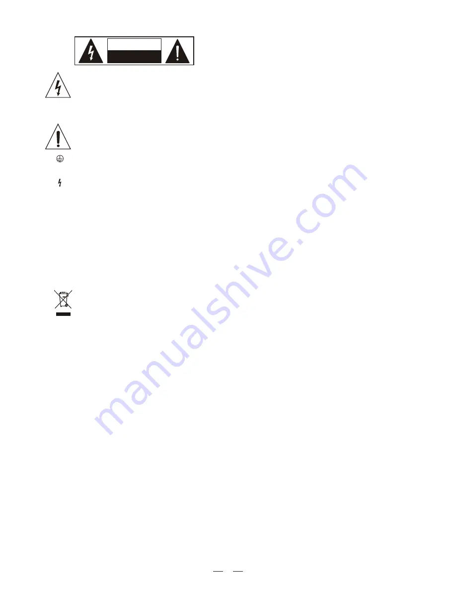
SAFETY RELATED SYMBOLS

CAUTION

RISK OF ELECTRIC SHOCK

DO NOT OPEN

This symbol, wherever used, alerts you to the pre-
sence of un-insulated and dangerous voltages with-
in the product enclosure. These are voltages that 
may be sufficient to constitute the risk of electric 
shock or death.

Protective Ground Terminal

AC mains (Alternating Current)

Hazardous Live Terminal

ON:

    Denotes the product is turned on.

This symbol, wherever used, alerts you to impo-
rtant operating and maintenance instructions. 
Please read.

OFF:  

Denotes the product is turned off. 

WARNING

Describes precautions that should be observed to 
prevent the possibility of death or injury to the user.

CAUTION

Describes precautions that should be observed to 
prevent damage to the product.

˙

Protective Ground

˙

Operating Conditions

IMPORTANT SAFETY INSTRUCTIONS

˙

Cleaning

˙

Servicing

˙

Power Cord and Plug

the recommended fuse type as indicated in this 
manual. Do not short-circuit the fuse holder. Before 
replacing the fuse, make sure that the product is 
OFF and disconnected from the AC outlet.

Before turning the product ON, make sure that it is 
connected to Ground. This is to prevent the risk of 
electric shock.

Never cut internal or external Ground wires. Likewise, 
never remove Ground wiring from the Protective 
Ground Terminal.

Always install in accordance with the manufacturer's 
instructions.

To avoid the risk of electric shock and damage, do 
not subject this product to any liquid/rain or moisture. 
Do not use this product when in close proximity to 
water.

Do not install this product near any direct heat source.

Do not block areas of ventilation. Failure to do so 
could result in fire.

Keep product away from naked flames.

Read these instructions

Follow all instructions

Keep these instructions. Do not discard.

Heed all warnings.

Only use attachments/accessories specified by the 
manufacturer.

Do not tamper with the power cord or plug. These are 
designed for your safety.

Do not remove Ground connections!

If the plug does not fit your AC outlet seek advice from 
a qualified electrician.

Protect the power cord and plug from any physical 
stress to avoid risk of electric shock.

Do not place heavy objects on the power cord. This 
could cause electric shock or fire.

When required, either blow off dust from the product 
or use a dry cloth.

Do not use any solvents such as Benzol or Alcohol.
For safety, keep product clean and free from dust.

Refer all servicing to qualified service personnel only.

Do not perform any servicing other than those instruc-
tions contained within the User's Manual.

˙

Fuse

To prevent fire and damage to the product, use only 

No user serviceable parts inside.

˙

Power Supply

Ensure that the mains source voltage (AC outlet) 
matches the voltage rating of the product. Failure 
to do so could result in damage to the product and 
possibly the user.

Unplug the product before electrical storms occur 
and when unused for long periods of time to reduce 
the risk of electric shock or fire.

˙

External Connection

Always use proper ready-made insulated mains 
cabling (power cord). Failure to do so could result 
in shock/death or fire. If in doubt, seek advice from 
a registered electrician.

˙

Do Not Remove Any Covers

Within the product are areas where high voltages 
may present. To reduce the risk of electric shock do 
not remove any covers unless the AC mains power 
cord is removed.

Covers should be removed by qualified service 
personnel only. 

WARNING

1

Disposing of this product should not be 
placed in municipal waste and should be  
Separate collection.

Summary of Contents for BETAVERB

Page 1: ...βVERB β 24 32 BIT DIGITAL EFFECTS User s Manual LTO R R www altoproaudio com Version 2 3 September 2005 English English ...

Page 2: ...t away from naked flames Read these instructions Follow all instructions Keep these instructions Do not discard Heed all warnings Only use attachments accessories specified by the manufacturer Do not tamper with the power cord or plug These are designed for your safety Do not remove Ground connections If the plug does not fit your AC outlet seek advice from a qualified electrician Protect the powe...

Page 3: ...are with you our work and our dreams paying attention to your suggestions and your comments Following this idea we create our products and we will create the new ones From our side we guarantee you and we will guarantee you also in future the best quality the best fruits of our continuous researches and the best prices Our LTO βVERB is the result of many hours of listening and tests involving comm...

Page 4: ... CONNECTION 5 4 1 Audio Connections and Power Up a Audio Connections b Power Up Setting 4 2 Analog a Levels Setting 4 3 Installation a Mono Use of βVERB b Standard Use c Application Examples Line Instrument Mixer 4 4 Operational Overview 5 ALGORITHMS DESCRIPTIONS 10 5 1 Reverbs a Halls b Rooms c Plates 5 2 Modulations a Tremolo b Chorus c Flange d Rotary Speakers 5 3 Delay 5 4 Effects Functional D...

Page 5: ...N OFF Digital Mix ON OFF 8 9 10 11 12 13 14 18 6 7 1 2 3 4 5 15 17 16 DIGITAL MIX ON OFF UTIL EDIT ESC ENTER DOWN UP ON OFF POWER 24 Ñ32 BIT DIGITAL EFFECTS VERB SAVING PRESET PROCESS OVERFLOW PROCESS OVERFLOW R LTO OUTPUT LEVEL INPUT LEVEL MIX 10 OFF WET DRY 10 OFF 18 24 30 6 12 CLIP Purchasing LTO βVERB you purchased a very powerful effect processor easy to use and contained in a very efficient ...

Page 6: ...and eff functions available within EDIT MENU When Digital Mix ON OFF is on the analog mix potentiometer must be positioned on fully Wet When Digital Mix ON OFF is off Digital Mix ON OFF LED is turned off the Dry Wet Mix Potentiometer for Analog Dry Wet Mixing 16 can be used to analogically adjust the balance between the Dry signal coming into the input and the Wet one coming from βVERB after the e...

Page 7: ... itself When the MONO ON OFF switch is manually set to ON position physically the INPUT 2 will be routed also on the internal INPUT 1 line b Power Up Setting After making your connections turn on the system power using this procedure Before turning on the βVERB power check if All connections been have made correctly The volume controls of the amplifier or mixer are turned down Insert the Power plu...

Page 8: ...CESS OVERFLOW R LTO OUTPUT LEVEL INPUT LEVEL MIX 10 OFF WET DRY 10 OFF 18 24 30 6 12 CLIP 18 24 30 6 12 CLIP 18 24 30 6 12 CLIP 7 MIXING CONSOLE Aux Return Aux Send DIGITAL MIX ON OFF UTIL EDIT ESC ENTER DOWN UP ON OFF POWER 24 Ñ32 BIT DIGITAL EFFECTS VERB SAVING PRESET PROCESS OVERFLOW PROCESS OVERFLOW R LTO OUTPUT LEVEL INPUT LEVEL MIX 10 OFF WET DRY 10 OFF 18 24 30 6 12 CLIP STEREO Set manually...

Page 9: ...knob 3 Play the source 5 Depending on the input sensitivity of the mixer s channels or Aux Returns the OUTPUT knob of the βVERB should be set somewhere between 2 00 and fully clockwise 5 00 6 Turn up the AUX RETURN level until the desired level of effect in the mix is reached The control in the chain that may need to be set to a low level is the Aux Return on the mixer itself Here is where should ...

Page 10: ... name will be maintained as name of the new preset th Pressing ENTER as confirmation of the 6 character the new preset will be stored with the new name There is no possibility to correct a confirmed character if necessary to change again the name repeat the storing process from the beginning Once terminated the sequence above on the display the name of the new stored preset will appear and the sys...

Page 11: ...configuration has not yet stored in a memory location If you do not want to store the modified preset accepting to lose the new configuration passing to a next preset or turning off the βVERB you can proceed with the βVERB use also if that LED is ON Reverb in nature is the sum of a large number of distinct echoes generated by the reflection of the original sound against obstacles i e walls In a re...

Page 12: ...on b Chorus The Chorus effect tries to recreate the illusion of more than one instrument from a single instrument sound Two musicians playing the same instrument never play in perfect unison both time and pitch wise In order to build up the proper illusion using an electronic device the original sound is summed with a slightly delayed and detuned version of itself Instead of a constant pitch devia...

Page 13: ...eflections min max in 127 steps Percentage of fast reflections min max in 127 steps Percentage of reverb min max in 127 steps Percentage of effect min max in 100 steps Percentage of direct signal min max in 127 steps Reverse Time 40 705 ms in 200 steps Pre delay 0 254 ms step 2 ms Density min max in 127 steps Switchable effect high pass filter 50Hz 1 kHz step 1 3 oct Switchable effect low pass fil...

Page 14: ...igh damp 1 kHz 16 kHz step 1 3 oct Switchable low damp 50 Hz 1 kHz step 1 3 oct Time 1 0 995 ms step 5 ms Time 2 0 995 ms step 5 ms Time 3 0 995 ms step 5 ms Decay 1 min max in 127 steps Decay 2 min max in 127 steps Decay 3 min max in 127 steps Volume 1 min max in 127 steps Volume 2 min max in 127 steps Volume 3 min max in 127 steps Pan pot 1 min max in 127 steps Pan pot 2 min max in 127 steps Pan...

Page 15: ...ax in 128 steps Depth Left min max in 240 steps Depth Right min max in 240 steps Switchable effect high pass filter 50Hz 1 kHz step 1 3 oct Switchable effect low pass filter 1 kHz 16 kHz step 1 3 oct Phase Effect Direct Reverse Oscillator Type Sine Ramp Effect Mode Stereo Mono Sum Percentage of effect min max in 127 steps Percentage of direct signal min max in 127 steps Switchable low pass cyl 50H...

Page 16: ...l 4 Hall 5 Hall 6 Hall 7 8000 8000 12500 12500 12500 12500 12500 2500 50 50 50 50 50 50 50 50 0 72 72 50 0 0 72 50 156 156 156 156 156 154 156 154 0 0 0 0 0 0 0 0 127 127 127 127 127 127 127 127 75 9 0 75 9 9 0 0 87 113 53 116 93 103 99 16 50 50 50 50 50 50 50 50 34 32 31 28 31 31 30 32 4000 4000 16000 12500 12500 12500 16000 4000 30 8 8 28 0 0 0 15 12 5 5 63 0 0 0 61 127 127 127 127 127 127 127 1...

Page 17: ...00 6300 80 400 400 60 60 80 8000 127 OFF 127 10000 PING PONG DELAY Low Pass Hz H Damp Hz L Damp Hz Time ms Decay HP Eff Hz LP Eff Hz Vol Eff Vol Dir 100 ms 6300 63 100 50 80 5000 127 127 8000 200 ms 6300 63 200 50 80 5000 127 127 8000 300 ms 6300 63 300 50 80 5000 127 127 8000 400 ms 6300 63 400 50 80 5000 127 127 8000 MULTI DELAY Low Pass Hz H Damp Hz L Damp Hz Time1 ms Time2 ms Time3 ms Decay 1 ...

Page 18: ...y R HP Eff Hz LP Eff Hz Phase Eff Type Osc Mode Eff Vol Eff Vol Dir Sin 1 80 3 2 171 194 96 88 80 Inverse 10000 Sin Stereo 127 127 12500 Sin 2 Sin 3 Ramp 1 Ramp 2 Ramp 3 H Damp Hz 80 7 12 59 56 72 57 80 Inverse 10000 Sin Stereo 127 127 12500 80 116 116 26 36 43 31 80 Inverse 10000 Sin Stereo 127 127 12500 80 12 11 59 102 99 96 80 Inverse 10000 Sin Stereo 127 127 12500 80 56 41 33 49 77 91 80 Inver...

Page 19: ... 20 45 127 2000 110 0 Fast 1 1600 60 65 105 39 8 13 127 2000 107 0 Fast 2 1600 60 64 143 110 20 45 127 2000 111 0 UTILITY MENU Factory 1 64 User 65 128 Load Preset init Enter Esc Store Preset User 65 128 Edit Name 2 Enter Esc Enter Edit Name 1 Edit Name 6 Enter Enter Esc Enter Esc Midi Setup Output Att Channel OFF 1 16 OMNI 0 127 0 Mute 127 0dB Up Down Vol Eff 100 100 100 100 Esc Esc ...

Page 20: ...RY Yes 1KHz 16KHz Bypass step 1 3 oct Bypass 50Hz 1KHz step 1 3 oct 1KHz 16KHz Bypass step 1 3 oct 0 254 ms step 2ms 0 254 ms step 2ms 0 254 ms step 2ms 0 127 Min Max 0 127 Min Max 0 127 Min Max Bypass 50Hz 1KHz step 1 3 oct 1KHz 16KHz Bypass step 1 3 oct Min 0 Max 127 Volume Early Reflection 0 127 Volume Fast Reflection 0 127 Volume Reverb 0 127 Volume Effect 0 100 Volume direct signal 0 127 Reve...

Page 21: ...ms Up Down PreDelay Density High Pass Eff Reverse Mode Volume Eff Linear Exp Gated Volume Effect 0 127 Bypass 50Hz 1KHz step 1 3 oct Effect DRY Volume Dir Volume direct signal 0 127 Yes No 36 636 ms step 3ms 0 127 Min Max Low Pass Eff 1KHz 16KHz Bypass step 1 3 oct ...

Page 22: ...ass 50Hz 1KHz step 1 3 oct 0 995 ms step 5ms Up Down H Damp L Damp Time R Time L Decay L Decay R High Pass Eff Low Pass Eff Link L R Vol Eff 0 127 Min Max 0 127 Min Max Bypass 50Hz 1KHz step 1 3 oct Volume Effect 0 127 1KHz 16KHz Bypass step 1 3 oct Effect DRY Volume Dir Volume direct signal 0 127 Yes No 0 995 ms step 5ms OFF ON ...

Page 23: ...t 1KHz 16KHz Bypass step 1 3 oct Bypass 50Hz 1KHz step 1 3 oct 0 995 ms step 5ms Up Down H Damp L Damp Time Decay High Pass Eff Low Pass Eff Vol Eff 0 127 Min Max Bypass 50Hz 1KHz step 1 3 oct Volume Effect 0 127 1KHz 16KHz Bypass step 1 3 oct Effect DRY Vol Dir Volume direct signal 0 127 Yes No ...

Page 24: ...Vol Eff 0 127 Min Max Bypass 50Hz 1KHz step 1 3 oct Volume Effect 0 127 Effect DRY Volume Dir Volume direct signal 0 127 Yes No 0 995 ms step 5ms Decay 1 0 127 Min Max Decay 3 0 127 Min Max Up Down Time 3 0 995 ms step 5ms 0 127 Min Max 0 127 Min Max 0 127 Min Max 0 127 MinL Max R Min R Max L Volume 2 Volume 3 Panpot 1 Panpot 2 Panpot 3 0 127 MinL Max R Min R Max L 0 127 MinL Max R Min R Max L ...

Page 25: ... L Damp Rate L Rate R Depth L Depth R High Pass Eff Low Pass Eff Phase Chorus Type Osc Effect Mode 0 240 Min Max 0 240 Min Max Bypass 50Hz 1KHz step 1 3 oct Sin Ramp Stereo Mono Sum 1KHz 16KHz Bypass step 1 3 oct Direct Invers Effect DRY Volume Dir Volume direct signal 0 127 Yes No Up Down 0 128 Min Max 0 128 Min Max ...

Page 26: ...z 1KHz step 1 3 oct Volume Effect 0 127 Effect DRY Volume Dir Volume direct signal 0 127 Yes No Depth R Decay R 0 127 Min Max Up Down Depth L Direct Invers Sin Ramp Low Pass Eff Phase Tremolo Type Osc Effect Mode Volume Eff Stereo Mono Sum 0 128 Min Max 0 128 Min Max 0 240 Min Max 0 240 Min Max 1KHz 16KHz Bypass step 1 3 oct Bypass 50Hz 1KHz step 1 3 oct ...

Page 27: ...L Rate R Depth L Depth R High Pass Eff Low Pass Eff Phase Chorus Type Osc Effect Mode Vol Eff 0 240 Min Max 0 240 Min Max Bypass 50Hz 1KHz step 1 3 oct Sin Ramp Stereo Mono Sum Volume Effect 0 127 1KHz 16KHz Bypass step 1 3 oct Direct Invers Effect DRY Volume Dir Volume direct signal 0 127 Yes No Up Down 0 128 Min Max 0 128 Min Max ...

Page 28: ...p Horn Volume Hron Volume Cyl Volume Eff No Effect DRY Yes Start Enter Esc Up Down 50Hz 16KHz Bypass step 1 3 oct Bypass 50Hz 16KHz step 1 3 oct 0 128 Min Max 0 128 Min Max 0 240 Min Max 0 240 Min Max 0 127 Min Max 0 127 Min Max 0 127 Min Max 0 127 Min Max Volume Effect 0 100 Volume direct signal 0 127 Volume Dir ...

Page 29: ...H Damp L Damp H Damp L Damp Low Pass Cyl High Pass Horn Rate Cyl Rate Horn Depth Cyl Depth Horn Mod Amp Cyl Mod Amp Horn Vol Cyl Vol Horn Vol Eff Vol Dir H Damp H Damp H Damp L Damp Time L Time R Decay L Decay R High Pass eff Low Pass eff Link L R L Damp Time Decay High Pass eff Low Pass eff Vol Eff Vol Eff L Damp Time1 Time 2 Time3 Decay 1 Decay 2 Decay 3 Volume 1 Volume 2 Volume 3 PanPot 1 PanPo...

Page 30: ... Reverb Legend Legend 0 1 0 13 Dry Wet 1KHz 16KHz Bypass step 1 3 oct 0 127 0 13 0 14 0 127 0 127 0 127 0 127 0 127 0 127 0 14 0 13 0 127 0 127 0 127 0 127 0 100 0 127 Master output volume for all effects 1KHz 16KHz Bypass step 1 3 oct Bypass 50Hz 1KHz step 1 3 oct 0 254 ms step 2ms 0 254 ms step 2ms 0 254 ms step 2ms 0 127 0 127 0 127 Bypass 50Hz 1KHz step 1 3 oct tuning Volume Early Reflection V...

Page 31: ...nput Low Pass Input 0 13 0 13 0 13 1KHz 16KHz Bypass step 1 3 oct 1KHz 16KHz Bypass step 1 3 oct 1KHz 16KHz Bypass step 1 3 oct H Damp H Damp H Damp 1KHz 16KHz Bypass step 1 3 oct 1KHz 16KHz Bypass step 1 3 oct 1KHz 16KHz Bypass step 1 3 oct L Damp L Damp L Damp Bypass 50Hz 1KHz step 1 3 oct Bypass 50Hz 1KHz step 1 3 oct Bypass 50Hz 1KHz step 1 3 oct Time L Time 1 Time 2 Time 3 Time 0 995ms Step 5...

Page 32: ...ss step 1 3 oct 1KHz 16KHz Bypass step 1 3 oct 1KHz 16KHz Bypass step 1 3 oct H Damp H Damp L Damp L Damp Bypass 50Hz 1KHz step 1 3 oct Bypass 50Hz 1KHz step 1 3 oct Bypass 50Hz 1KHz step 1 3 oct Bypass 50Hz 1KHz step 1 3 oct Bypass 50Hz 1KHz step 1 3 oct Bypass 50Hz 1KHz step 1 3 oct Bypass 50Hz 1KHz step 1 3 oct Rate L Rate L Rate Cyl Rate R Rate R Rate Horm Depth R Depth R Depth Horn Decay R De...

Page 33: ...y Power Rating Alphanumeric LCD Display Keyboard VU meter Size Dimensions Net Weight 44 kOhms 15 dBu 4 4V RMS 22 dBu 63mV RMS 150 Ohms 17 dBu on 600 Ohms 5 5V RMS 20 Hz 20 kHz 0 1 1 dB 90 dB A wtg 20 Hz 20kHz 700 μS 0 03 1kHz 6 dB VU meter level 46 875 kHz 1 bit Sigma Delta 12 Mips Input Output Thru 24 32 bits 5 poles DIN female Microprocessor Photocoupled 3 pole IEC grounded Servo controlled stab...

Page 34: ...TO of 1 year from the purchase date if you have completed the Warranty Registration Card in time 3 3 During the warranty service may repair or replace this product at its own option at no charge to you for LTO parts or for labor in accordance with the right side of this limited warranty 3 4 This warranty does not apply to the damages to this product that occurred as the following conditions Normal...

Page 35: ...313737 email alto altoproaudio com Fax 886 4 22346757 c All rights reserved to ALTO All features and content might be changed without prior notice Any photocopy translation or reproduction of part of this manual without written permission is forbidden Copyright 2005 SEIKAKU GROUP SEIKAKU TECHNICAL GROUP LIMITED ...

Reviews: