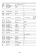
Class
Part No
Description
Specification
Insert location
Remark
│ ├
0002
RD00219 SMD precise resistor 1/10W
20.0K
Ω
±1% 0603
R42,R43,R44,R45,R38,R39,R40
│ ├
0003
RD00294 SMD precise resistor 1/10W
24.9K
Ω
±1% 0603
R46
│ ├
0004
CI00063
SMD ceramic capacitor 0603
470PF/50V NPO ±5
﹪
C42,C43
│ ├
0005
CI00075
SMD ceramic capacitor 0603
0.1uF/50V Y5V +80,-20%
C14,C15,C16,C17,C26,C27,C28,C29,C30,
C31,C32,C33,C100
│ ├
0006
SF00056 transistor
MMBT3904(SOT23)/(PHI)
TR9
│ ├
0007
RD00282 SMD precise resistor 1/10W
1.00K
Ω
±1% 0603
R8,R31,R32
│ ├
0008
RD00274 SMD precise resistor 1/10W
100
Ω
±1% 0603
R24,R53
│ ├
0009
RD00301 SMD precise resistor 1/10W
12.1K
Ω
±1% 0603
R12
│ ├
0010
RD00290 SMD precise resistor 1/10W
47.5K
Ω
±1% 0603
R23,R25,R26,R27,R29,R30
│ ├
0011
RD00264 SMD precise resistor 1/10W
60.4K
Ω
±1% 0603
R41
│ ├
0012
RD00224 SMD precise resistor 1/10W
100K
Ω
±1% 0603
R7,R100
│ ├
0013
CI00058
SMD ceramic capacitor 0603
82PF/50V NPO ±5%
C12
│ ├
0014
RD00003 SMD fixed resistor 1/8W
10
Ω
±5% 0805
R35,R36
│ ├
0015
RD00030 SMD fixed resistor 1/8W
6.8K
Ω
±5% 0805
R33,R34
│ ├
0016
SG00210 SMD integrated circuit
LM339DT/(ST)
IC6
│ ├
0017
SE00011 SMD rectifier diode
RLS4148 0.5A (LL-34)
D2,D3,D4,D5,D6,D7
│ ├
0018
CI00030
SMD ceramic capacitor 0805
1uF/16V Y5V-0805(2012)
C20,C21
│ ├
0019
RD00292 SMD precise resistor 1/10W
1.00M
Ω
±1% 0603
R37
│ ├
0020
CI00268
SMD ceramic capacitor-RS 0603
47PF/50V NPO ±5
﹪
C10
│ ├
0021
HK04167 PC board
P-EQU215PU-
Ⅱ
-AI
│ │ ├
0001
HA01920 wire-RS
6mm
J5,J2,J23,J29
│ │ ├
0002
HA01922 jump
8mm
J3,J4,J6,J7,J8,J17,J22,J26
│ │ ├
0003
HA01925 jump
10mm
J9,J10,J11,J12,J13,J14,J18,J19,J21,
J24,J27,J28,J15
│ │ ├
0004
HA01928 jump
12mm
J16
│ │ ├
0005
HA01937 jump
18mm
J20,J25
│ │ ├
0006
RA01268 fixed resistor 1/4W
2K
Ω
R49,R50
│ │ ├
0007
RA01113 fixed resistor 1/4W
10K
Ω
R3,R4,R5,R13,R14
│ │ ├
0008
RA01125 fixed resistor 1/4W
56K
Ω
R1,R2
│ │ ├
0009
RA01111 fixed resistor 1/4W
100K
Ω
R16,R19,R21,R22
│ │ ├
0010
CB00242 electrolytic capacitor
22uF/35V
φ
5*11mm
C1,C2,C3,C4,C5,C6,C8,C13,C40,C41,
C46,C19,C22
│ │ ├
0011
CB00235 electrolytic capacitor
100uF/25V
φ
6*11mm
C52,C53
│ │ ├
0012
CB00193 electrolytic capacitor
47uF/16V
φ
6*7mm
C54
│ │ └
0013
HB01231 PCB-RS
EQU15PU-
Ⅱ
(1*2)_VER070322
│ └
0022
SG00558 integrated circuit-RS
UTC4580M(4580M )(SOP8)/(YW)
IC1,IC2,IC3,IC4,IC5
├
0040
HK04169 PC board-RS
P-EQU215POW-
Ⅱ
│ ├
0001
HB01229 PCB
EQU15POW-
Ⅱ
(4*2)_VER040428
│ ├
0002
RA01111 fixed resistor 1/4W
100K
Ω
R1
│ ├
0003
CC00039 mylar capacitor
0.1uF/100V 3%
C1,C2,C3,C4,C5,C6,C7,C8,C9
│ ├
0004
SA00098 rectifier diode
1A/400V IN4004
D1,D2,D3,D4
│ ├
0005
CB00065 electrolytic capacitor
470uF/25V
φ
10*16mm
C12,C13
│ ├
0006
CB00134 electrolytic capacitor
1000uF/35V 105
℃
SH
φ
12*21mm
C10,C11
│ ├
0007
SD00077 integrated circuit-RS
L7815CV(TO220)/(ST/MOROCCO)
U1
│ ├
0008
SD00079 integrated circuit
L7915CV(TO220)/(ST)
U2
│ ├
0009
MI00256
heat-sink
25*15*10.6-1PIN SCL-2020
│ ├
0010
MG00162 screw
M3*8
│ ├
0011
MF00037 washer
φ
3.2*
φ
5*0.8t
│ ├
0012
NC00167 mica-RS
13*18(
φ
3.6)TO-220
│ ├
0013
HC00172 connector(male)
3P 3.96mm 180°
CN1,CN2,CN3
│ ├
0014
HI00121
slide switch
SCH-12-07
SW1
│ ├
0015
HA01931 jump
16mm
J1
│ ├
0016
HA02190 signle terminal wiring
150mm
│ ├
0017
AC00603 lead free soldering bar
S100
│ └
0018
SA00175 Schottky barrier diode
1A/40V 1N5819
Reverse solder
between PIN3 of
7815 & GND
├
0041
HK04116 PC board-RS
P-EQU231VUSW-
Ⅱ
-DIP
│ ├
0001
HI00162
push-button switch
2 paragraphs 6p PS-22E8552L
SW1,SW2,SW3
│ ├
0002
HI00163
push-button switch
2 stage 12P PS-42E85
SW4
│ ├
0003
SA00053 L.E.D
φ
3 round(red)long foot 26mm
LED4,LED7,LED9
│ ├
0004
SA00052 L.E.D
φ
3 round(green)long foot 26
LED3,LED6,LED8
│ ├
0005
SA00054 L.E.D
3m/m round(yellow)long foot 26
LED1,LED2,LED5
│ ├
0006
NI02049
LED spacer support
LEDS-14 14mm
│ ├
0007
HK04115 PC board
P-EQU231VUSW-
Ⅱ
-SMD
│ │ ├
0001
HB01238 PCB
EQU231VUSW-
Ⅱ
(2*3)_VER040921
│ │ ├
0002
RD00214 SMD precise resistor 1/10W
10.0K
Ω
±1% 0603
R1,R2,R3,R4,R5,R6,R7,R8,R9
--- 21 ---
Summary of Contents for EQU215
Page 1: ...www altoproaudio com Version 1 0 MODEL EQU215 MKII V2 Revised on Jan 2010...
Page 5: ...3 Block Diagram 3...
Page 6: ...4 Schematic Diagram 4...
Page 7: ...5...
Page 8: ...6...
Page 9: ...7...
Page 10: ...8...
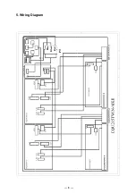
Page 11: ...Blue Black Red PT 5 Wiring Diagram 9...
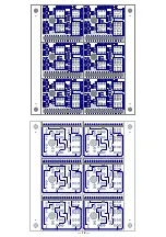
Page 12: ...6 PCB Layout 10...
Page 13: ...11...
Page 14: ...12...
Page 15: ...13...
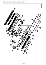
Page 20: ...MODEL No EQU215 MKII V2 8 Exploded View Mechanical Parts List 18...


