
Page 6
CLARKE TECHNOLOGY Image 20 Operator's Manual
INSTRUCCIONES DE SEGURIDAD
INSTRUCCIONES PARA LA SEGURIDAD DEL OPERADOR
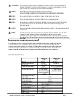
WARNING
AVERTISSEMENT
AVISO
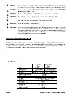
PELIGRO:
Si no siga las instrucciones que siguen la palabra PELIGRO, se pueden
causar lesiones graves, incluso mortales. Lea y siga todas las instrucciones
PELIGRO que se encuentran en el libro y en la máquina.
AVISO:
Si no siga las instrucciones AVISO, se pueden causar lesiones sea al
operador sea a otro persona y/o daños materiales. Lea y siga todas las
indicaciones AVISO que se encuentran en el libro y en la máquina.
CUIDADO:
Si no siga las instrucciones señaladas por la palabra CUIDADO, se puede
estropear la máquina o causar daños materiales en su entorno. Lea y siga
todas las indicaciones CUIDADO que se encuentran en el libro y en la
máquina.
AVISO
:
Para evitar el riesgo de incendio, de choque eléctrico o de lesiones, sírvase
respetar las instrucciones siguientes:
1.
No deje nunca la máquina si está conectada con la red. Desconecte la máquina cuand no la usa
y antes de efectuar el mantenimiento.
2.
Para evitar un choque eléctrico, use la máquina sólo dentro.
3.
Esta máquina no es un juguete. Tenga cuidado si la usa cuando hay niños.
4.
Confórmese estrictamente a las instrucciones de utilización descritas en este libro. Use sólo
los accesorios recomendados por el fabricante.
5.
Nunca opere la máquina si el cable de alimentación o el enchufe están dañados. Si la máquina
no funciona correctamente, si ha caído, si ha sido dañada, si se ha quedado fuera o si se ha
quedado inmersa en el agua, mándela a uno de nuestros centros técnicos.
6.
Nunca tire de la máquina usando el cable de alimentación. Nunca transporte la máquina
usando el cable. Nunca use el cable como empuñadura. No bloquee el cable al cerrar una
puerta, no arrastre el cable por encima de una arista de la pared. Siempre levante el cable
por encima de la máquina. Aleje al cable de las fuentes de calor.
7.
Para desconectar la máquina, tire del enchufe y no del cable.
8.
Nunca toque la máquina o el enchufe con manos húmedas.
9.
Nunca introduzca objetos en la aberturas. Nunca use la máquina si una abertura está obstruida por
un objeto. Quite a las aberturas el polvo, las felpas, los cabellos que podrían reducir el caudal de
aire.
10. El operador mantendrá siempre une distancia de seguridad suficiente con respecto a las aberturas
y las partes móviles de la máquina. Tenga particularmente cuidado de los cabellos, ropas
holgadas, dedos, etc.
11. Nunca aspire ningún objeto incandescente (cigarrillos, cerillas, cenizas calientes).
12. Nunca use la máquina sin bolsa y/o filtro de polvo.
13. Ponga todos los mandos en la posición ‘OFF’ antes de desconectar la máquina.
14. Sea muy prudente cuando limpia una escalera.
15. Nunca use la máquina en el entorno directo de líquidos inflamables y carburantes (gasolina, por
ejemplo). Nunca aspire líquidos inflamables o combustibles líquidos.
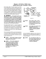
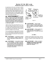
16. La máquina debe ser conectada con una caja de enchufe puesta a tierra y conectada con la red,
con todas las reglas del arte. Véase ‘Instrucciones para la conexión’.
GUARDE CUIDADOSAMENTE ESTAS INSTRUCCIONES


