
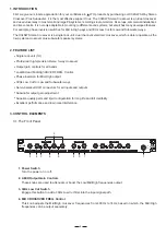

11. AC Inlet
This connector is used to connect the supplied main cord. Please don't plug power
cable into unit and AC power if
voltage has not been properly set.
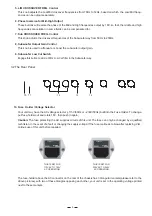
12. L/M/H Output Connectors
These balanced XLR connectors are used to output the Low/Mid/high frequencies signals.
13. Stereo Input Connectors
These balanced XLR connectors are used to input the program sources.
14. Subwoofer Output Connector
This balanced XLR connector is used to connect your subwoofer amplifier.
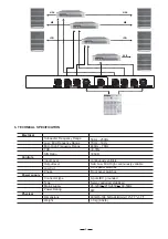
4.2 Audio Connection
The
presents with balanced XLR connectors, and it can be interfaced by several ways to
LTO X34SW Active Crossover
support a variety of applications without any signal loss.
4. INSTALLATION & CONNECTION
4.1 Mains Connection
Please ensure that the
LTO X34SW Active Crossover is set to the correct supply voltage before plug
the
ging
power cord into the wall outlet, use the same fuse as marked on the fuse holder at the AC
connection socket.
power
The mains connection of the
LTO X34SW Active Crossover is made by using the enclosed mains cord and a
standard IEC receptacle. It meets all of the international safety certification requirements.
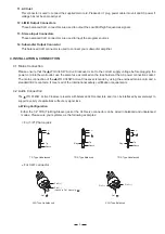
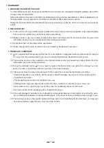
a. Wiring Configuration
Either the 1/4" TRS (Tip-Ring-Sleeve) jack or the XLR servo connector can be wired in balanced and unbalanced
modes. Please wire your systems as the following examples:
6
For 1/4" Phone jack
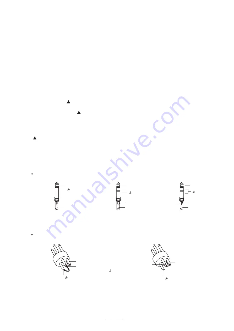
For XLR connector
XLR Type Unbalanced
XLR Type
alanced
B
Pin3 (-)
Pin2 (+)
Pin1 ( )
(Linked to Pin1 manually,
)
Pin1 ( )
Pin2 (+)
Pin3 (-)
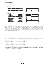
TS Type Unbalanced
Sleeve
Tip
+
TRS Type Balanced
Tip
Ring
Sleeve
+
-
TRS Type Unbalanced
Tip
Ring
Sleeve
+


