PARTITION
Partition assembly
It is important that the partition assembly is
completed at this stage - before the remaining
end panels and roof panels are fixed.
Gather all parts required for the partition
assembly.
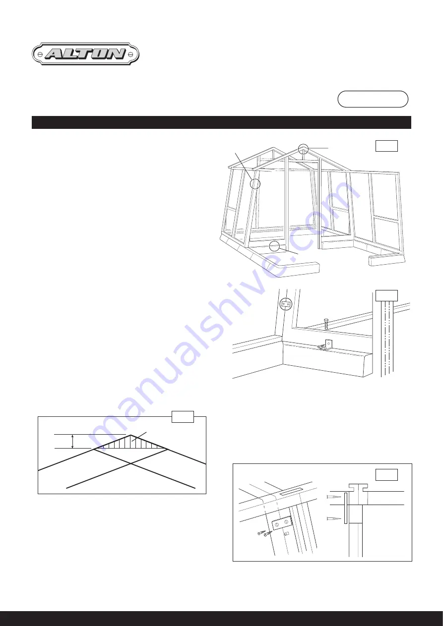
If you have not already done so, position
the partition concrete kerbs (same shape
as end kerbs. 2 x E689) so that they are
on a joint between two side frames. This
should be (dependent on position of
partition) 4’10
3
/
4
”/1493mm from the inside of the
end kerb to the centre of the partition footings.
Giving an approximately 5’/1.25 deep.
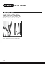
Remove and discard the coach screw from the
main building cill adjacent to the partition kerbs,
this will allow the partition to fit properly
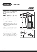
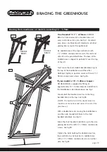
It is necessary to cut away the top point of the
partition frame to allow it to fit under the ridge
bar. Mark cut line as indicated in fig 2 and saw
off.
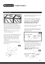
Offer up the partition section and check for fit
and square, secure to base kerbs with angle
brackets, using bolts and
3
/
4
”/19mm screws.
See fig 3
OPTIONAL
fig 1
see fig 3
see fig 4
see note 1
see fig 2
page 11
Frame
Remove this section
Frame
1
1
/
16
” 27mm
fig 2
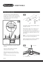
Secure the partition to the side panels with two
plates per side and 1”/25mm countersunk screws.
Repeat the instructions on the roof sections.
See fig 4.
NOTE 1:
If the partition is next to a ventaccess
fig 3
fig 4
Summary of Contents for Amateur 8'0" x 10'6"
Page 31: ...page 31...


