background image

YOUR NEW CEDAR GREENHOUSE 

Introduction

Thank you for buying an Alton Cedar Greenhouse.

Please read carefully through these instructions

before beginning to put your greenhouse up. 

Optional Extras

It is extremely important that you assemble your

optional extras in the correct position. Throughout

these instruction references will be made to each

optional extra. Please refer to the appropriate page

or leaflet for full details.

Safety advice

It is advisable that the greenhouse should be

assembled by two people. Particular care should

be taken when handling glass and the wearing of

gloves is strongly recommended. Favourable

weather conditions should be chosen. Do not try

to erect the building in windy conditions - the

panels are difficult to handle in high winds.

All side frames should be suitably propped until

the roof frames are secured.

Keep children and pets away until the work is

finished.

Take your time - rushing causes accidents.

Fitting service

Please call your local dealer if you would like to

have a quote for the erection of your greenhouse

by an installer.

Tools required to erect the greenhouse

Drill & bits (for pilot holes), screwdrivers (for slot

and posi-drive), spanners 10mm & 17mm, small

hammer, pliers, spirit level, step ladder, tape

measure, bradawl, mastic gun, saw & props.

Planning and preparation

All of the illustrations relate to a 10’6”/3.20m long

Amateur Greenhouse. For other models you will

have a greater or smaller number of Side and Roof

Sections for your chosen model.

Before you commence assembly of the frame it is

advisable to pre-determine the layout of individual

sections to ensure the roof vents are in the

position you require. To assist you in this each

section has been individually wrapped and

labelled. 

If you do not want to cut one of the roof cover

strips please avoid positioning a roof vent at either

end of the greenhouse.

A bradawl or drill should be used to pilot all screw

holes, especially on the shelving and staging, to

help prevent the timber from splitting. Sometimes

the pre-drilled holes in the frames can be blocked

- simply insert a screwdriver to clear them. 

Unpacking the greenhouse

Before removing all the packaging please note the

individual named pieces of greenhouse. This is not

only a convenient way to check you have all the

correct sections, but also to help you when

determining the layout and assembly of your

greenhouse. You will also notice all fixtures, nails,

screws, bolts etc., come pre-packed and labelled

for your convenience. Keep these in their bags

which will make identification easier.

If using a knife be careful not to cut into the cedar

wood.

Future Reference

Please keep these assembly instruction safe as you

may need them for reference in the future.

page 3

Summary of Contents for Amateur 8'0" x 10'6"

Page 1: ...8 Wide AMATEUR CEDAR GREENHOUSE PLEASE READ ALL INSTRUCTIONS BEFORE PROCEEDING ASSEMBLY INSTRUCTIONS 10 10...

Page 2: ...First Side Panel 7 Fixing the Plain Gable End 8 Fixing the remaining Side Panels 9 Fixing Door End Gable 10 PARTITION Partition Assembly 11 12 ROOF Preparation and Fixing of Ridge Bar 13 14 Fixing of...

Page 3: ...astic gun saw props Planning and preparation All of the illustrations relate to a 10 6 3 20m long Amateur Greenhouse For other models you will have a greater or smaller number of Side and Roof Section...

Page 4: ...is essential Extension Modules Partitions Simply extend your greenhouse either or both ends using a pre treated extension module s You remove an end gable bolt in the new extension then replace the en...

Page 5: ...buildings Over hanging branches can be a particular nuisance and should be avoided Choose a site where the greenhouse is relatively easy to get to and convenient to bring water to and possibly a supp...

Page 6: ...el The dimensions are given above Check the diagonal measurements both ways to ensure squareness As a result of the manufacturing process the kerbs can in some cases be uneven on the underside and may...

Page 7: ...rst side panel The bolts for fixing the frames are different lengths and are for specific locations Washers should always be fitted before the nut is put on Please note that when a low level vent is f...

Page 8: ...g a side section to the gable end the side vent is adjacent to the gable the bolts must be reversed so it s head is inside the channel of the lift up vent See fig 5 Use 3 off 23 4 70mm bolts washers a...

Page 9: ...rilled hole as shown in fig 8 FIXING SIDE PANELS Fixing the remaining side panels fig 9 fig 8 Fix the plastic tongue in the slot between the side panels This may be done from either the top or bottom...

Page 10: ...n fig 3 Use 3 off 23 4 70mm bolts washers and nuts plus the plastic covers page 10 Having fixed all the side sections offer the door gable end section to the assembly having first removed the transit...

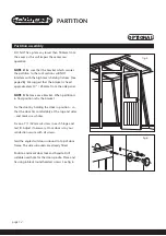
Page 11: ...discard the coach screw from the main building cill adjacent to the partition kerbs this will allow the partition to fit properly It is necessary to cut away the top point of the partition frame to a...

Page 12: ...inal position refix the bracket Fix the door by holding the door in position so that the door fits comfortably at the top and sides and mark screw holes Fix one 11 4 32mm csk screw in each hinge and t...

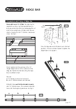
Page 13: ...ositions of the U shaped ridge brackets on the underside of the ridge bar Position the brackets along the ridge bar as indicated in fig 3 Measure a 1 5 432mm in from each end and b 2 65 8 778mm betwee...

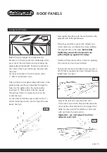
Page 14: ...xtent that it has a small upward curve in it fig 5 fig 6 page 14 Fixing Roof Panels Prior to commencing the assembly of the roof gather together all the necessary bolts washers nuts brackets and screw...

Page 15: ...upper edge of the bracket Position the bracket in the centre of the style and line up the bend with the mark Secure each bracket to the roof section with a 1 25mm round head screw Offer up the first...

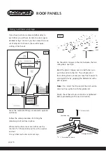
Page 16: ...3 4 70mm bolts and fix with a washer and nut Fit any other roof vents and vent caps 7 8 22mm 7 8 22mm fig 7 Fix the plastic tongue in the slot between the two roof panels See fig 8 Bend the plastic to...

Page 17: ...See fig 2 Fix the remaining roof cover strips as shown opposite in fig 3 If you have a roof vent adjacent to the gable you will have to cut away part of the strip to allow the vent to close Take care...

Page 18: ...4 off 11 4 32mm countersunk screws Measure a distance of 121 4 312mm down from the top of the side section to get the correct position of the end of each brace IF YOUR GREENHOUSE IS LONGER THAN 13 3...

Page 19: ...CE is supplied for fitting at approximately 10 3 04m intervals in addition to the Middle Brace described above See fig 2 Loosely bolt the double brace ties to the long bevelled block at the top See fi...

Page 20: ...or is vertical and then hold the metal top door track in position and mark its location on the frame Take the door away and fit the metal top door track Ensure the right hand end lines up with the out...

Page 21: ...nd of the channel cut into the door Fix with 2 off 3 4 19mm countersunk screws fig 5 see fig 7 see fig 8 fig 8 see fig 9 fig 7 fig 6 fig 9 Staple To fix the staple first measure up from the bottom of...

Page 22: ...your preferred position and hold the handle to the frame while you drill two 5mm screw holes into the door frame Where the drill has marked the inside of the handle drill two small pilot holes This w...

Page 23: ...at the bottom of the top louvre cill is at 21 535mm See fig 3 At this stage mark screw locations of vent make pilot holes with bradawl drill Secure with 3 4 19mm roundhead screws provided Fit bottom c...

Page 24: ...e correct position fix with 3 4 19mm countersunk screws We do not supply a casement stay when an Automatic Opener is supplied To fix an Automatic Opener refer to fig 4 plus the separate instructions s...

Page 25: ...d Using a 3 4 19mm screw See fig 4 Fix the support brackets fig 3 and joint bracket s fig 5 as required for the length of greenhouse Use 3 4 19mm screws Working from the downpipe end fix the guttering...

Page 26: ...n them The intermediate brackets can then be offered up so that the top of the brackets is just touching the string and fitted using the 40mm screws Where two pieces of shelving join there will need t...

Page 27: ...fig 6 You will need to modify shelving when fitting shelving in a building with middle brace Each end slat will have to be measured and cut to fit around the brace The shelving can then be secured to...

Page 28: ...these are fitted a string can be pulled taut between them The intermediate brackets can then be offered up so that the top of the brackets is just touching the string and fitted using the 40mm screws...

Page 29: ...e at the eaves with plastic glass stops which are fixed with screws Side and End glass All glass is held in on one side by a glazing groove and on the other by a timber beading and plastic glass stops...

Page 30: ...s 730mm 730mm 730mm 730mm 1422mm 838mm 1080mm 702mm 318mm 584mm Glass details for left hand partition section The right hand glass are exactly the same sizes Side Panel Door Panel Top Panels 3 3 1 1 2...

Page 31: ...page 31...
Page 32: ...ALTON Greenhouses Station Works Fenny Compton Southam Warwickshire CV47 2XB Telephone 01295 770795 Fax 01295 770819 10 10...

Reviews: